
Method for manufacturing fiber-reinforced plastic products
a technology of reinforced plastics and fibers, which is applied in the field of fiber-reinforced plastic products, can solve the problems of extending the flow time of resin inside the fiber preform, affecting the quality of fiber reinforced plastic products, so as to avoid dry glass fibers and/or white spots, and the effect of greater thickness
Patent Information
- Authority / Receiving Office
- US · United States
- Patent Type
- Applications(United States)
- Current Assignee / Owner
- Publication Date
- 2018-03-15
Smart Images
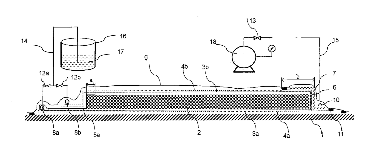
Figure 1 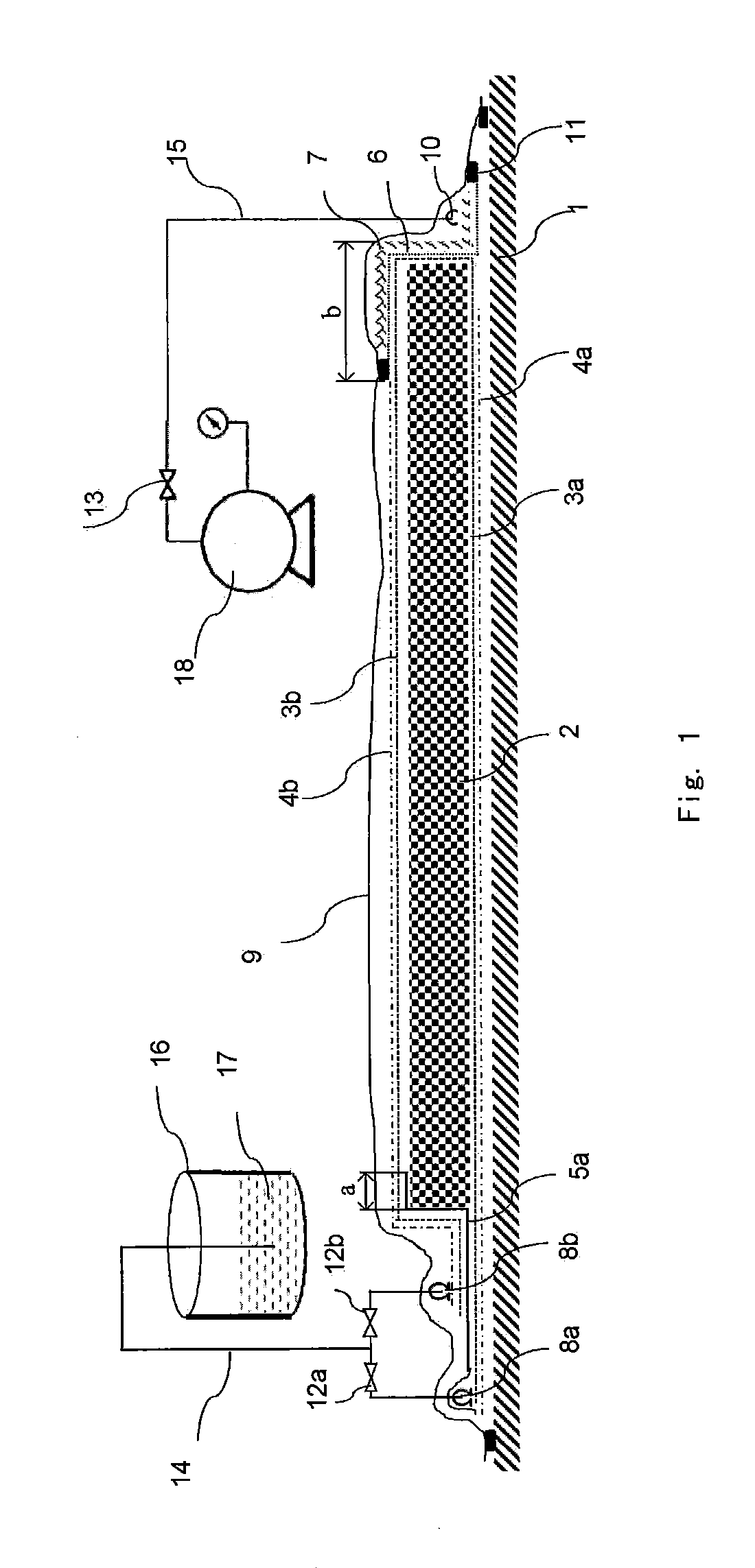
Figure 2 
Figure 3
Abstract
Description
FIELD OF INVENTION
[0001] The present invention relates to a method for manufacturing fiber-reinforced plastic products. Specifically, the present invention particularly relates to a method for molding fiber-reinforced plastic products with greater thicknesses by using a vacuum infusion process. The method is particularly suitable for the vacuum infusion molding of fiber-reinforced resin composite products such as polyurethane resin, epoxy resin and unsaturated resin, etc.BACKGROUND OF INVENTION
[0002] The vacuum infusion process has been widely used in the molding process of fiber-reinforced resin composite products. Generally speaking, the process is: first, disposing a certain number of layers of fibers on the mold in accordance with the design requirements to form a fiber preform, wherein the fiber preform may contain core materials such as foam, balsa or other reinforcing materials; in addition, there are also process materials such as a peel ply or release film, flow mesh, resin r...
Examples
first example
The First Example
[0067]Please refer to FIG. 1. Said figure shows the First Example according to the method for manufacturing fiber-reinforced plastic products of the present invention.
[0068]The method for manufacturing fiber-reinforced plastic products disclosed in the present invention is especially suitable for fiber preforms having relatively large thicknesses or that can hardly be impregnated by the resin, wherein, the so-called “fiber preforms having relatively large thicknesses” generally refers to the fiber preforms that can hardly have their entire thicknesses, which are determined by the property of the resin used therein, fully impregnated within the gel time of the resin. In the present invention, the resin can be selected from common resins such as polyurethane resin, epoxy resin, etc., as well as any uncommon resin that is suitable for impregnation of fiber preforms.
[0069]The following briefly introduces the steps of applying the method for manufacturing fiber-reinforce...
second example
The Second Example
[0077]Please refer to FIG. 2. Said figure shows the Second Example according to the method for manufacturing fiber-reinforced plastic products of the present invention.
[0078]As shown in FIG. 2, a stopper 19 was arranged on the air-pumping side of the fiber preform 2 or a mold 1 to replace the breathable felt 7 in the First Example. In FIG. 2, the stopper is in a triangle shape, but in the actual use, stoppers with other suitable shapes can also be selected.
[0079]The arrangements of the parts in the Second Example are identical to those of the First Example, except that the second peel ply 3b, the semi-permeable membrane 6 and the breathable felt 7 were disposed on the stopper 19, and a suction port 10′ was also arranged on the stopper 19.
[0080]Since in the Second Example, the stopper 19 was used in place of the second peel ply 3b, the semi-permeable membrane 6 and the breathable felt 7 that were disposed at the edge of the fiber preform 2, the required lengths of t...
third example
The Third Example
[0082]Please refer to FIG. 3. Said figure shows the Third Example according to the method for manufacturing fiber-reinforced plastic products of the present invention.
[0083]On the basis of step (c) of the Second Example, the second peel ply 3b, when disposed, may further extend to above the stopper 19 and the mold 1 so as to form a peel ply extension segment 3c as shown in FIG. 3 (shown as a dashed line in FIG. 3).
[0084](d1) A suction port 10″ was arranged over the peel ply extension segment 3c. A second film 5b was used to partly or completely cover the peel ply extension segment 3c and the suction port 10″, and to partly cover the fiber preform 2. The covered width of the fiber preform may be 10% to 70%, preferably 20% to 50%, of the width of the area without a flow mesh.
[0085](d2) A third peel ply 3d (shown as a dashed line in FIG. 3) was disposed on the second film 5b. As shown in FIG. 3, one side (i.e. the left side of FIG. 3) of the third peel ply 3d over the ...