
Pneumatic Tire
Patent Information
- Authority / Receiving Office
- US · United States
- Current Assignee / Owner
- Publication Date
- 2019-11-14
Smart Images
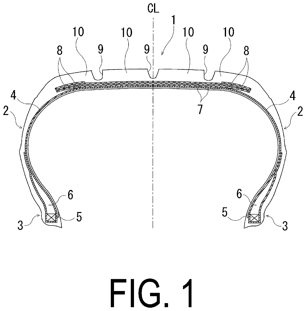
Figure 1 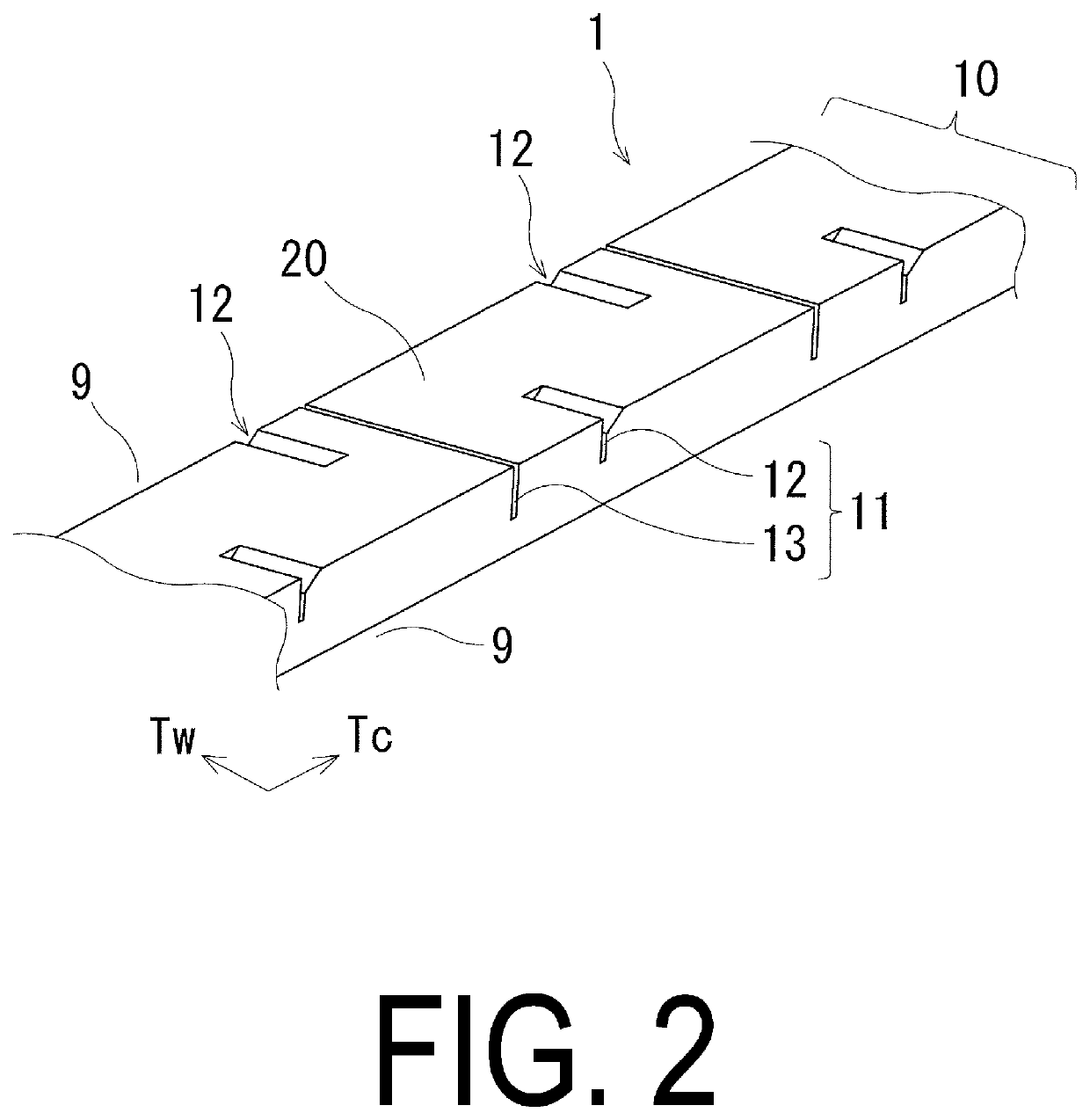
Figure 2 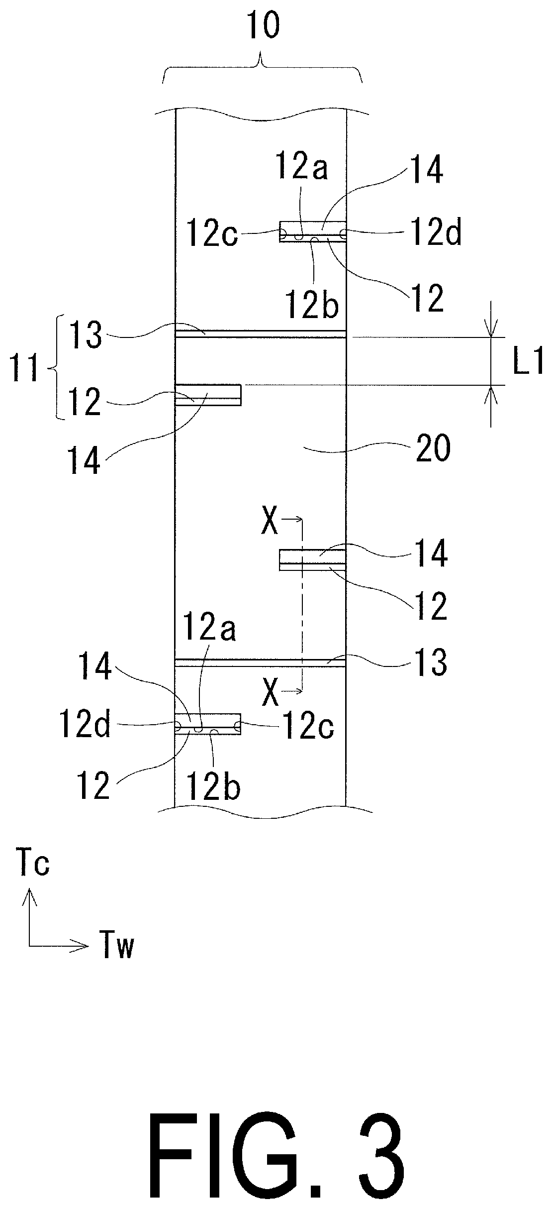
Figure 3
Abstract
Description
TECHNICAL FIELD
[0001] The present technology relates to a pneumatic tire and particularly relates to a pneumatic tire with improved wet performance by devising shapes of sipes provided in its tread portion.BACKGROUND ART
[0002] In general, a pneumatic tire includes a tread portion provided with a plurality of grooves and sipes to obtain wet performance. To improve braking performance which is an index of tire performance on a wet road surface, the grooves and the sipes are required to be improved in drainage performance.
[0003] As a method of improving drainage performance, providing a chamfer portion in an edge of a sipe provided in a tread portion has been proposed (e.g., Japan Unexamined Patent Publication No. 2016-88469). In this case, the chamfer portion serves as a discharge channel to improve drainage performance of a ground contact surface, so that improvement in tire wet performance is expected. Unfortunately, in a configuration in which a chamfer portion is simply added to a si...
Examples
examples
[0056]Using a pneumatic tire of the size 195 / 65R15 including, in a tread portion, a plurality of main grooves extending in the tire circumferential direction, and a plurality of ribs defined by a pair of the plurality of main grooves adjacent to each other, tires of Conventional Example, Comparative Examples 1, 2, and Examples 1 to 10 were produced according to Tables 1 and 2 showing: whether a chamfered sipe is provided; whether a non-chamfered sipe is provided; a distance L1 (mm) between a chamfered sipe and a non-chamfered sipe; a ratio (Nd / Cd) of a depth of a non-chamfered sipe to a depth of a chamfered sipe; a difference (θC-θN) between inclination angles of a chamfered sipe and a non-chamfered sipe; placement of a non-chamfered sipe (one side or both sides); a width of a non-chamfered sipe (uniform or gradual increase); a width Cw (mm) of an opening of a chamfered sipe in a ground contact surface; a cross-sectional shape of a chamfer portion; whether a non-chamfered sipe commu...