
Work machine and method for controlling work machine
Patent Information
- Authority / Receiving Office
- US · United States
- Current Assignee / Owner
- Publication Date
- 2022-03-03
Smart Images
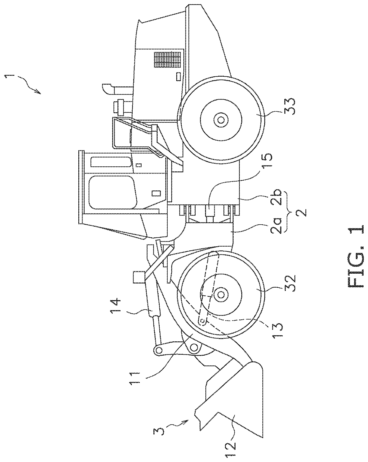
Figure 1 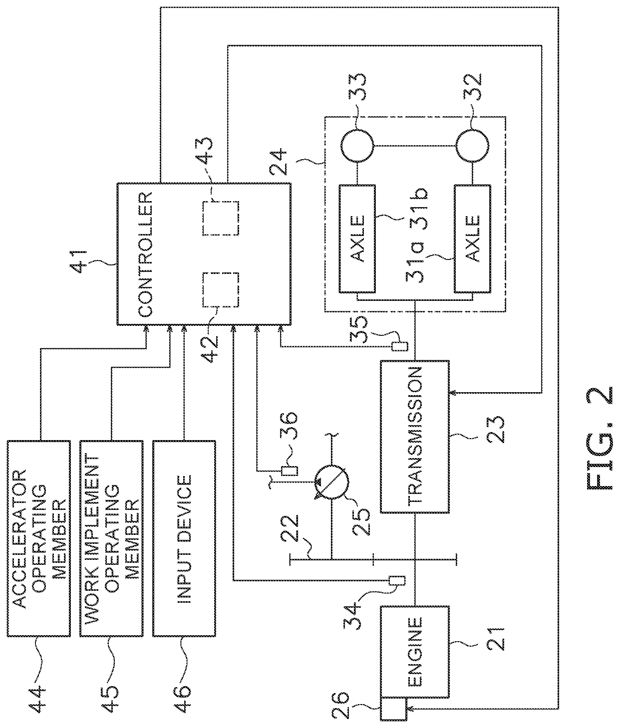
Figure 2 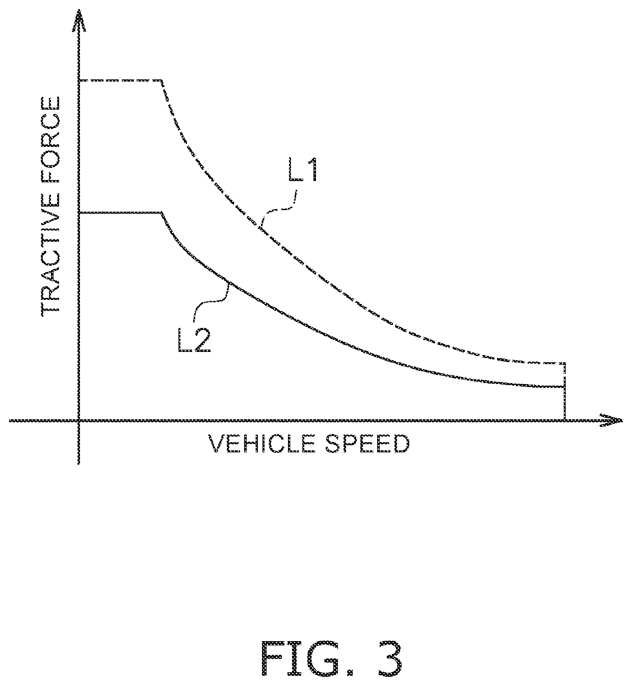
Figure 3
Abstract
Description
[0001] This application is a U.S. National stage application of International Application No. PCT / JP2020 / 009839, filed on Mar. 6, 2020. This U.S. National stage application claims priority under 35 U.S.C. § 119(a) to Japanese Patent Application No. 2019-062993, filed in Japan on Mar. 28, 2019, the entire contents of which are hereby incorporated herein by reference.BACKGROUNDField of the Invention
[0002] The present disclosure relates to a work machine and a method for controlling a work machine.Background Information
[0003] As described in WO 2005 / 024208 A1, a high-output mode and a low-output mode are set as control modes for the engine in a work machine. In the low-output mode, the maximum tractive force for each vehicle speed is reduced in comparison to the high-output mode. The switching between the low-output mode and the high-output mode is performed automatically in response to a load applied to the work machine. For example, the high-output mode is selected when the work machine...
Examples
Embodiment Construction
)
[0022]An embodiment of the present invention will be explained in detail with reference to the figures. FIG. 1 is a side view of a work machine 1 according to an embodiment of the present invention. As illustrated in FIG. 1, the work machine 1 includes a vehicle body 2 and a work implement 3.
[0023]The vehicle body 2 includes a front vehicle body 2a and a rear vehicle body 2b. The rear vehicle body 2b is connected so as to be able to turn to the left and right with respect to the front vehicle body 2a. The front vehicle body 2a and the rear vehicle body 2b are coupled by a hydraulic cylinder 15. The hydraulic cylinder 15 extends and contracts to turn the front vehicle body 2a to the left and right with respect to the rear vehicle body 2b.
[0024]The work implement 3 is used for work such as excavation. The work implement 3 is attached to the front vehicle body 2a. The work implement 3 includes a boom 11, a bucket 12, and hydraulic cylinders 13 and 14. The hydraulic cylinders 13 and 1...