
Construction vehicle with waste heat recovery
Patent Information
- Authority / Receiving Office
- US · United States
- Current Assignee / Owner
- Publication Date
- 2014-02-06
- Estimated Expiration
- Not applicable · inactive patent
Smart Images
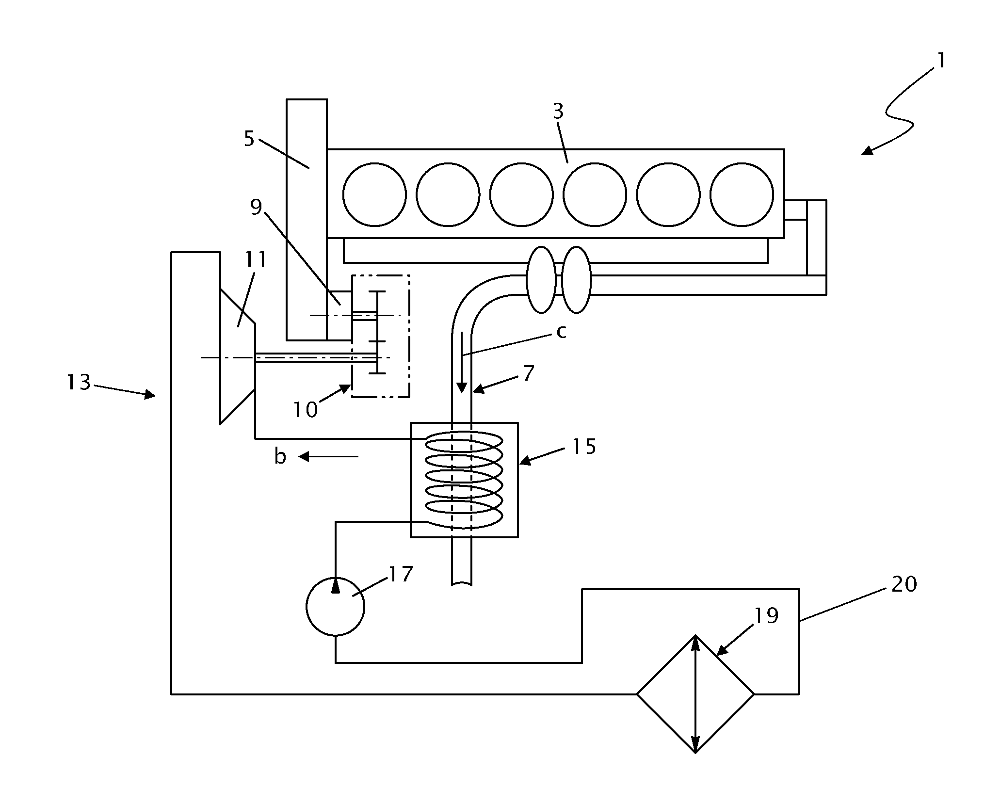
Figure 1 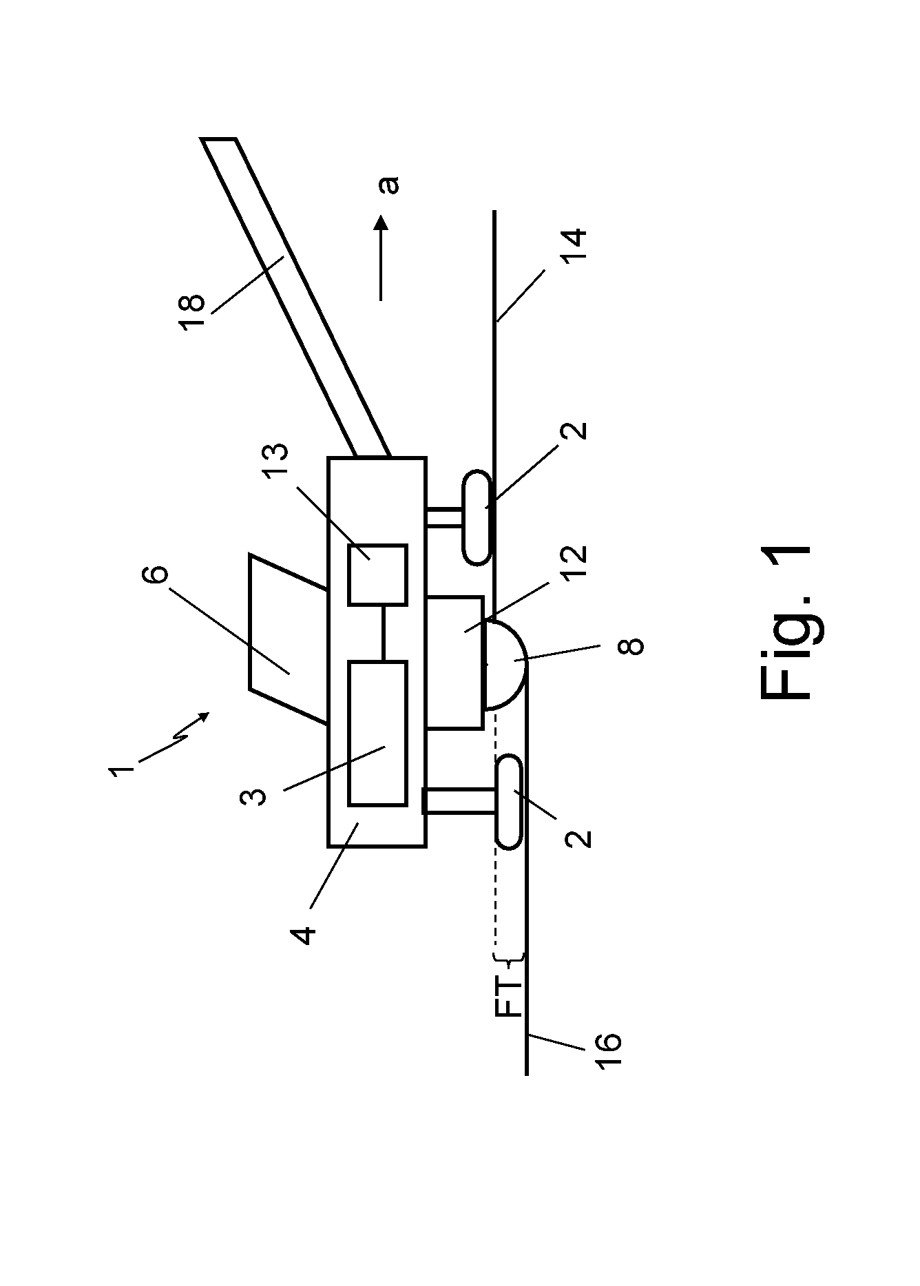
Figure 2 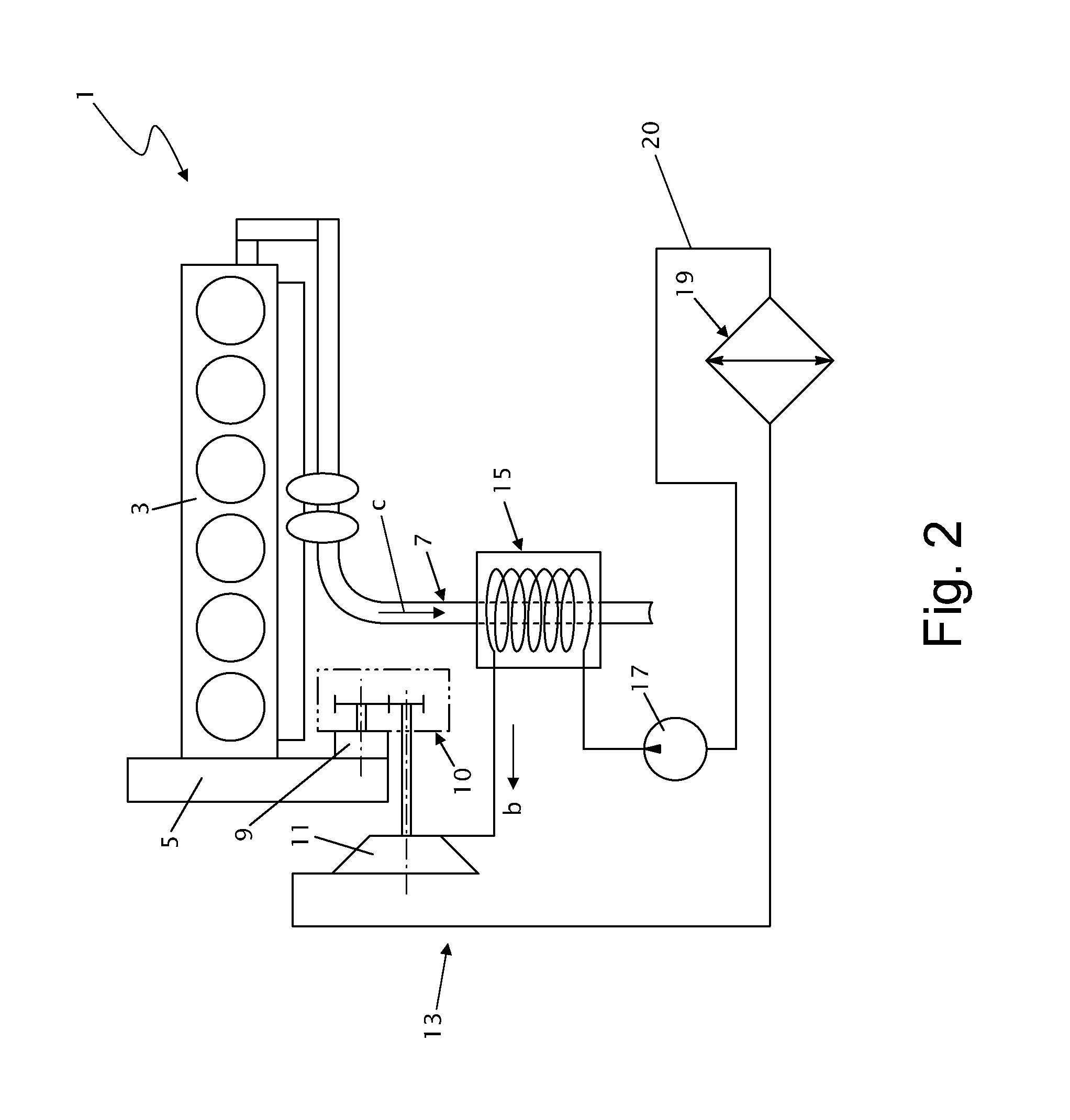
Figure 3
Abstract
Description
CROSS-REFERENCE TO RELATED APPLICATIONS
[0001] The present application claims priority under 35 U.S.C. §119 of German Patent Application No. 10 2012 015 267.1, filed Jul. 31, 2012, the disclosure of which is hereby incorporated herein by reference in its entirety.FIELD OF THE INVENTION
[0002] The present invention relates to a construction vehicle, in particular, a landfill compactor (landfill construction), also known as refuse compactor, or a road milling machine (road construction), having a main drive comprising at least one internal combustion engine by means of which at least part of the operating power needed to run the construction vehicle is provided.BACKGROUND OF THE INVENTION
[0003] Such construction vehicles typically always comprise an engine, in particular, an internal combustion engine, for traction and also for driving working implements such as milling drums, conveyors, hydraulic pumps, compactors, etc., mounted on the construction vehicle. The internal combustion engine ...
Examples
Embodiment Construction
[0031]FIG. 1 illustrates the basic construction of an exemplary construction vehicle 1 for ground processing, in this particular case a road milling machine. The construction vehicle 1 in FIG. 1 is configured for milling off an upper layer of the road surface to a milling depth FT. Essential components of the construction vehicle 1 are a machine frame 4, a chassis with a total of four caterpillar tracks 2 mounted on lifting columns on the machine frame 4, the lifting columns being vertically adjustable, an operator station 6 and a working implement, which in this specific case is a milling drum 8 mounted in a drum housing 12. The milling depth FT can be varied by vertically adjusting the lifting columns so that, for example, the distance of the underside of the vehicle down to the road surface is vertically variable. The milling drum 8 is disposed in the horizontal plane with its axis of rotation R perpendicular to the machine direction “a” of the construction vehicle 1. In the work...