
Assembly system based on a ball anchoring device
Patent Information
- Authority / Receiving Office
- US · United States
- Current Assignee / Owner
- Publication Date
- 2005-01-11
- Estimated Expiration
- Not applicable · inactive patent
Smart Images
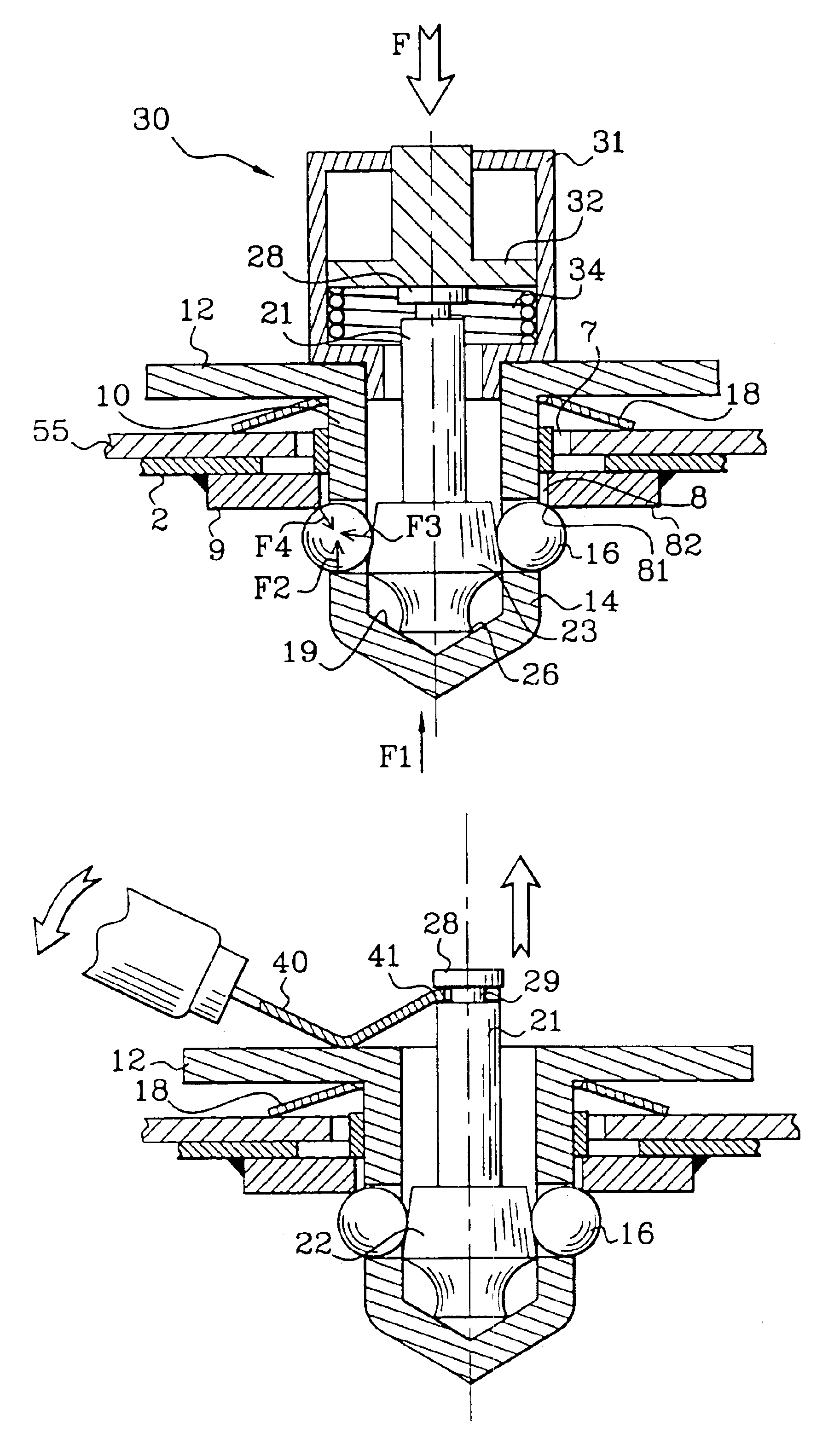
Figure 1 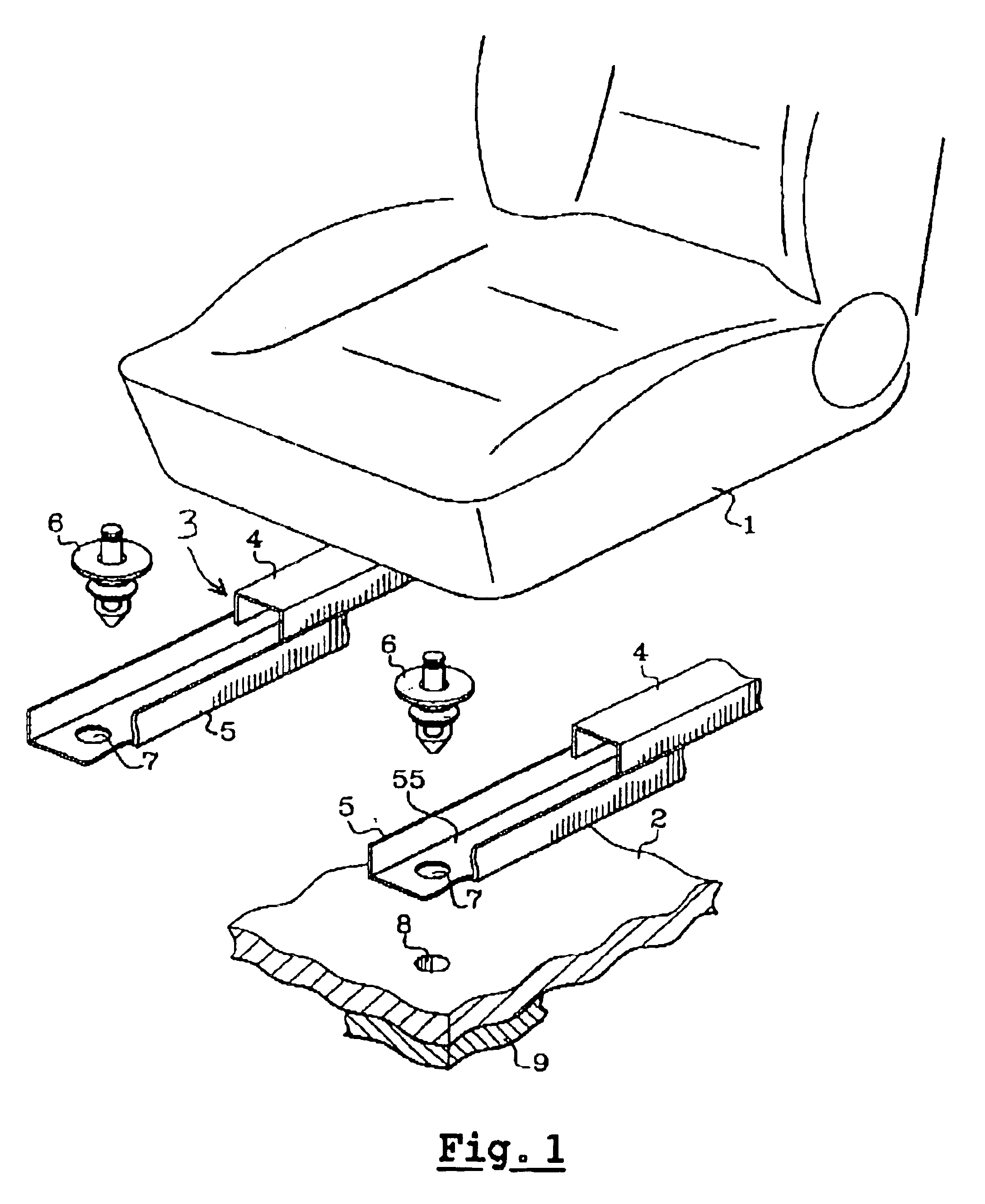
Figure 2 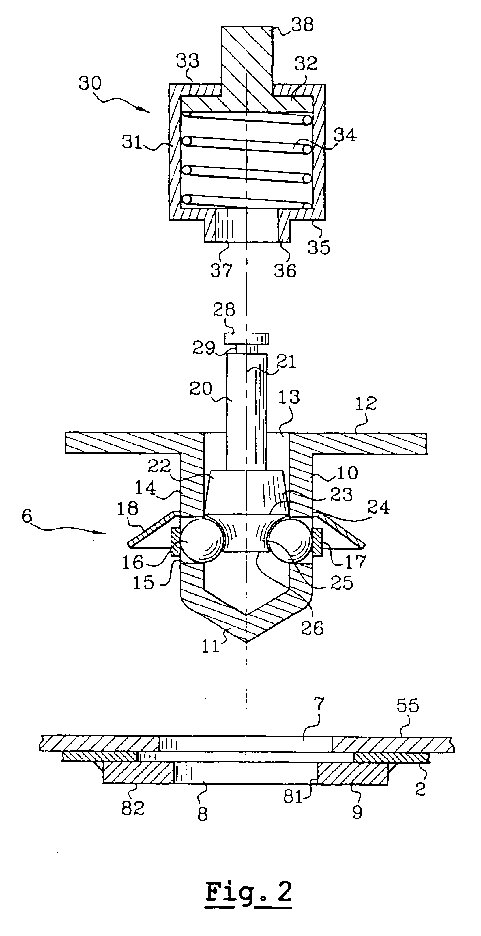
Figure 3
Abstract
Description
FIELD OF THE INVENTIONThis invention concerns an attaching system of the ball lock type, which can be used more particularly, but not exclusively, to attach an automobile vehicle seat supporting structure to the floor of the said vehicle.BACKGROUND OF THE INVENTIONTo make such an attachment, for example to secure to the floor a rail element for longitudinal seat position adjustment, a means of attachment by screwing is commonly used, either by screwing a bolt into a nut joined to the floor, or screwing a nut onto a threaded stud joined to the said floor. Consequently, it is obligatory to perform a screwing operation when putting the seat in place in the vehicle, which is not always practical if the bolt heads or nuts are poorly accessible to conventional screwing tools.In other cases, particularly when the connection of the seat to the floor must be readily separable, for example in the case of the rear attachments of seats with tilting seat pans, or with completely removable seats,...
Examples
Example
Refer to the appended drawings in which:
FIG. 1 is a partial perspective and exploded view of the seat and the elements for assembling it to the floor,
FIG. 2 is a cross-sectional view of the attaching device before installation, offered up above the parts to be assembled, along with the installation tool,
FIGS. 3 to 5 illustrate the subsequent phases in the making of the assembly,
FIG. 6 illustrates the removal of the attaching device,
FIG. 7 provides a similar view to FIG. 2, in another embodiment, where the device is premounted on the first part to be assembled.
BRIEF DESCRIPTION OF THE INVENTION
The drawing in FIG. 1 shows a vehicle seat 1 that is to be mounted on the floor 2 of the said vehicle by means of a set of rails 3 allowing longitudinal adjustment of the seat position. In a way known in itself, the frame of the seat pan is fixed to the upper rail elements 4, and the seat is usually supplied with its set of rails ready to be mounted on the floor 2. The lower rail elements 5 are...