
Modular structure for temporary exhibitions
a module and temporary exhibition technology, applied in the field of modular can solve the problems of difficult to keep these electrical connections contained within the structure, slow and laborious process of assembling the structure for temporary exhibitions, and inconvenient transportation of structures, etc., to achieve the effect of convenient transportation, simple structure, and cheap and versatil
Patent Information
- Authority / Receiving Office
- US · United States
- Patent Type
- Patents(United States)
- Current Assignee / Owner
- Publication Date
- 2011-07-05
- Estimated Expiration
- Not applicable · inactive patent
Smart Images
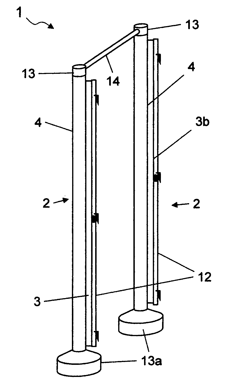
Figure 1 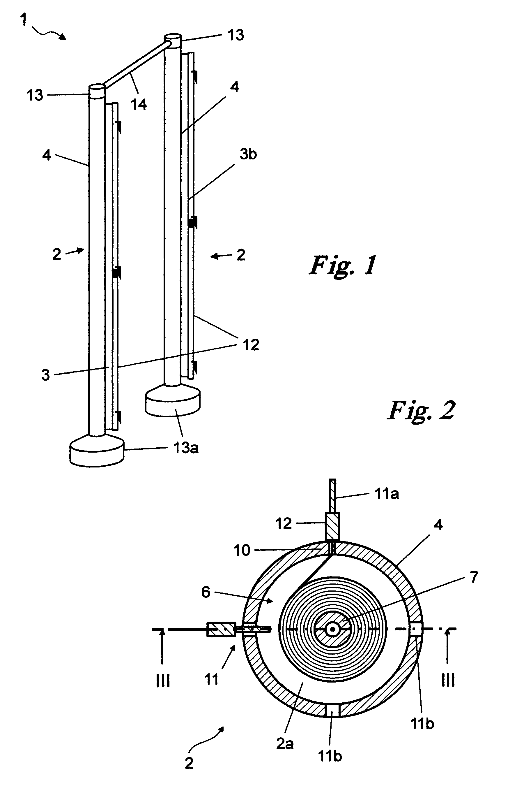
Figure 2 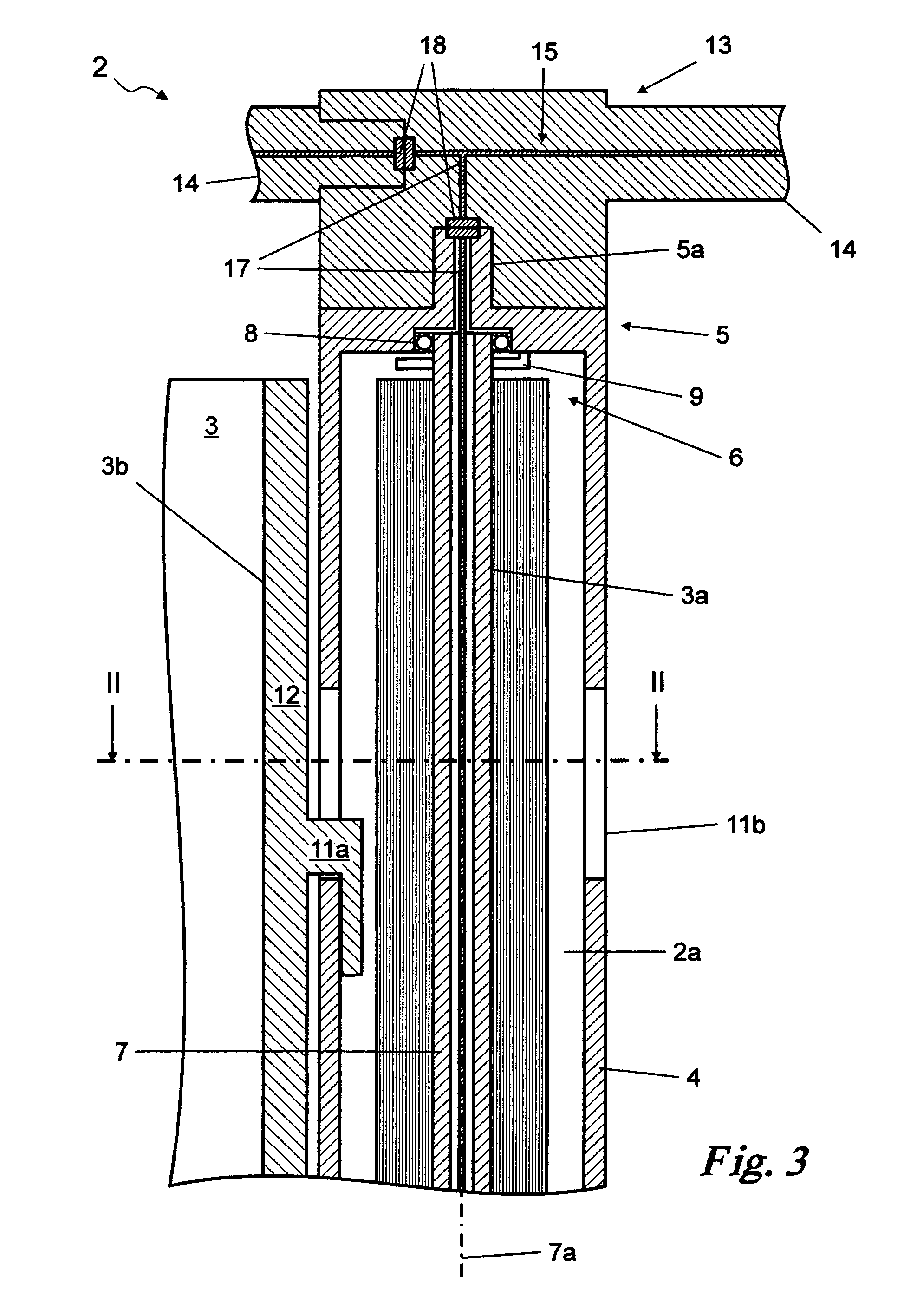
Figure 3
Abstract
Description
BACKGROUND OF THE INVENTION
[0001] 1. Field of the Invention
[0002] This invention relates to a modular structure for temporary exhibitions of the type comprising at least one shaft component.
[0003] 2. Brief Description of the Prior Art
[0004] As it is known, various structures currently exist for making stands at fairs and the like.
[0005] More specifically, various structures exist that are made of a series of modular plates that can be assembled. These plates can then be fastened to the ground through joining methods or appropriate plinths.
[0006] These components can be assembled at will to create a stand for exhibitions in fairs or for other similar temporary exhibitions. They are made from polymer materials or cardboard or something similar.
[0007] The prior art described above has some considerable drawbacks.
[0008] Assembling structures for temporary exhibitions becomes a slow and laborious process.
[0009] Another drawback arises from the fact these structures can be quite inconvenient to tr...
Examples
Embodiment Construction
[0030]With reference to the Figures, the modular structure according to the invention is generally referred by number 1.
[0031]In summary, this comprises at least one shaft component 2, at least one sheet 3 with at least one fixed end 3a, fastened to the shaft component 2, and at least one free end 3b broadly opposite the fixed end 3a.
[0032]In particular, the shaft component 2 contains an internal cavity 2a and is in effect a hollow prismatic strip 4, preferably shaped as a cylinder or quadrangle, with diameter between 5 and 25 cm and with wall thickness of between 0.5 and 3.0 mm.
[0033]The strip 4 should be made from metal but could also be from polymer materials.
[0034]The shaft component 2 comprises two end sections 5 level with the bases of the prismatic strip 4.
[0035]The end sections 5 also comprise a joining mechanism 5a, which can allow the ends 5 to be joined to a finishing component 13 such as a plinth 13a in stone, metal or another material.
[0036]The said joining mechanism 5...