
Clutch release mechanism with a device for compensating for lack of precision in a friction clutch of a motor vehicle
a technology of friction clutch and release mechanism, which is applied in the direction of mechanical actuator clutch, clutch, mechanical apparatus, etc., can solve the problem of limiting the extent to which the outer ring can be deflected from its centered position, and achieve the effect of minimal space and minimal cos
Patent Information
- Authority / Receiving Office
- US · United States
- Patent Type
- Patents(United States)
- Current Assignee / Owner
- Publication Date
- 2006-02-14
- Estimated Expiration
- Not applicable · inactive patent
Smart Images
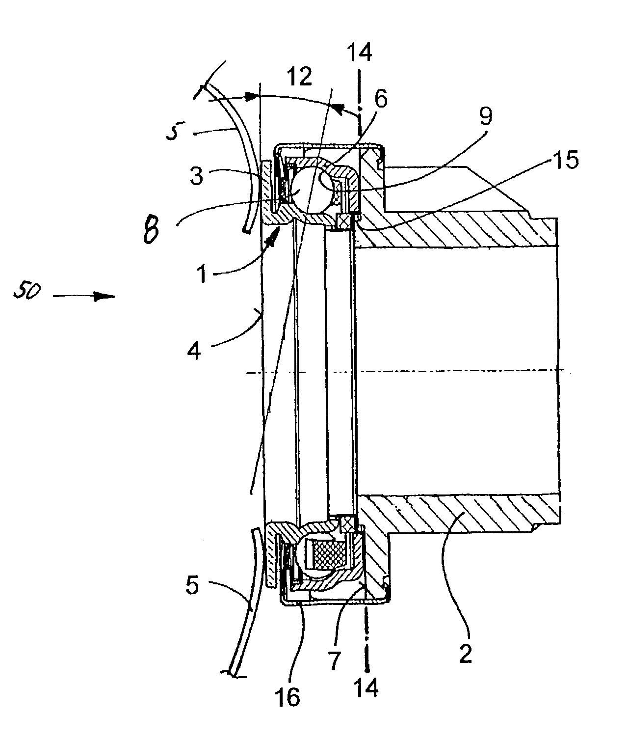
Figure 1 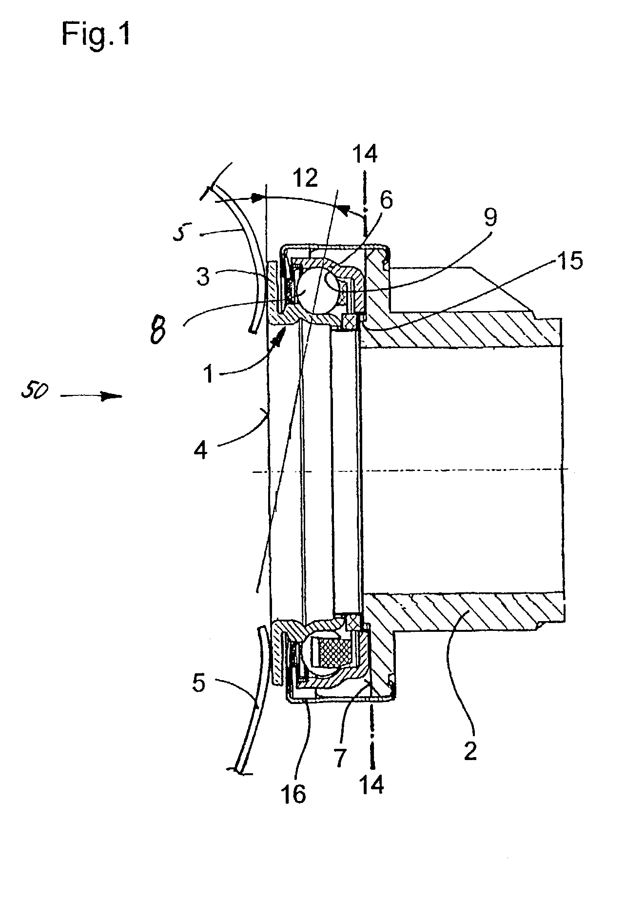
Figure 2 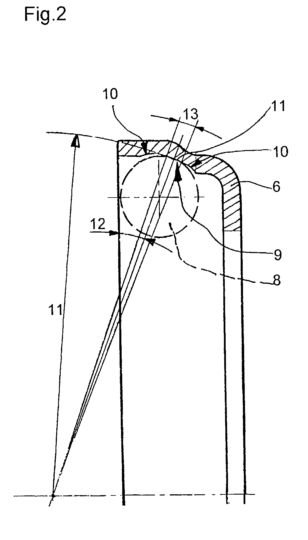
Figure 3
Abstract
Description
BACKGROUND OF THE INVENTION
[0001] 1. Field of the Invention
[0002] The invention relates to a clutch release mechanism for actuating a friction clutch between an internal combustion engine and a transmission of a motor vehicle. This mechanism is installed as concentric assembly around a guide sleeve mounted on a transmission shaft, comprising a release bearing with an inner ring and an outer ring as well as a sliding sleeve, where one of the rings, preferably the inner ring, is in working connection with a release spring of the friction clutch and the outer ring is in working connection with the sliding sleeve. The assembled release mechanism has a first device for compensating for a tilt of the center axis of the friction clutch with respect to the center axis of the guide sleeve and / or for a wobbling eccentricity of the release spring and a second device for compensating for an offset between the previously mentioned center axes.
[0003] 2. Description of the Related Art
[0004] DE 199 12 ...
Examples
Embodiment Construction
[0013]FIG. 1 shows a clutch-release mechanism 50 for actuating a friction clutch using a release spring 5. The release mechanism 50 has a release bearing 1, which is a ball bearing with an inner ring 3, balls 8, and an outer ring 6. The inner ring 3 rests by a contact surface 4 against the tongues of the release spring 5. The outer ring 6 has a sliding surface 7 indirectly or directly in common with a sliding sleeve 2 in a plane 14 transverse to the center axis of the release bearing 1. The sliding sleeve has a ring-shaped stop 15 for the outer ring 6 of the release bearing 1. A clamp 16 connects the release bearing 1 to the sliding sleeve 2 to form a structural unit.
[0014]In FIG. 2, the outer ring 6 has a race 9 which includes a ring-shaped surface with a first race radius 10, an intermediate ring-shaped surface with a second race radius 11, and an inner ring-shaped surface, again with the first race radius 10. As the balls 8 rotate in the outer ring 6, they can move within a defle...