
Current limit circuit and power supply including same
a current limit circuit and power supply technology, applied in the direction of electric variable regulation, process and machine control, instruments, etc., can solve the problems of low voltage, replete with parasitic error terms, and difficult direct signal processing, so as to reduce the duty cycle of the primary switch
Patent Information
- Authority / Receiving Office
- US · United States
- Patent Type
- Patents(United States)
- Current Assignee / Owner
- Publication Date
- 2007-08-07
Smart Images
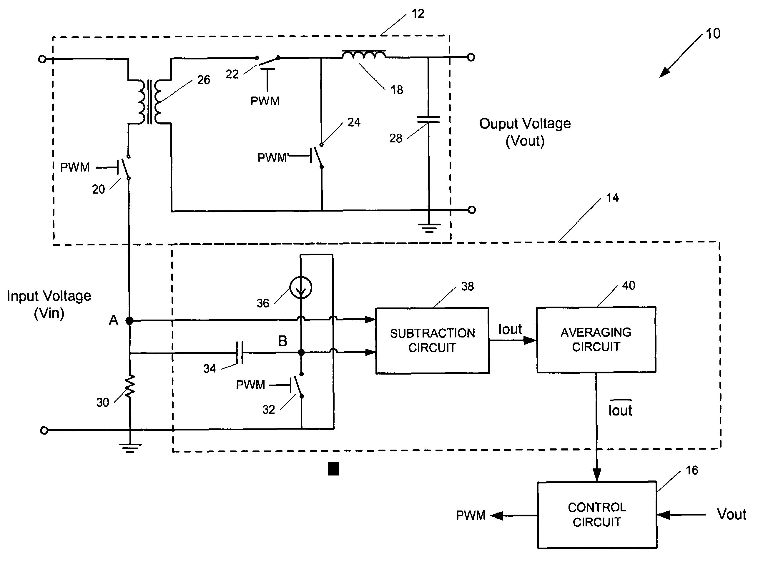
Figure 1 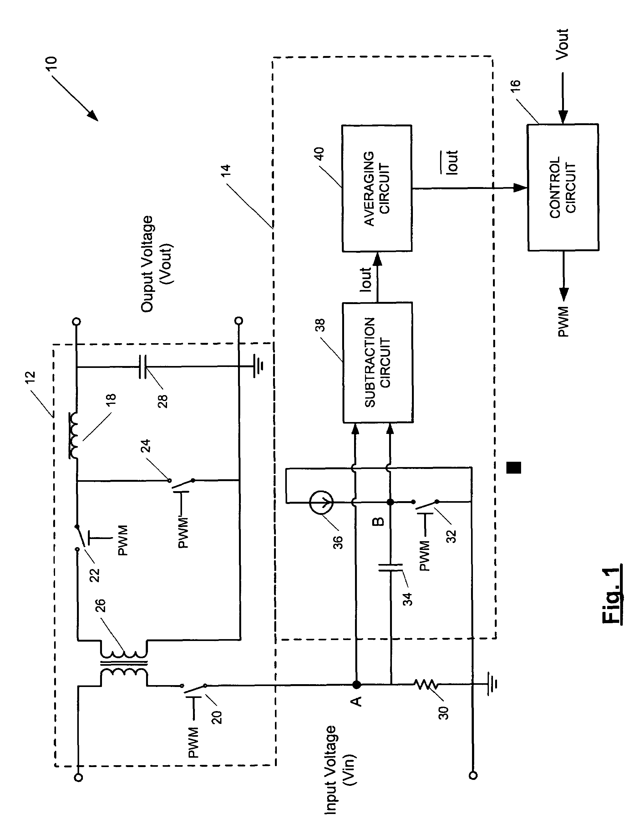
Figure 2 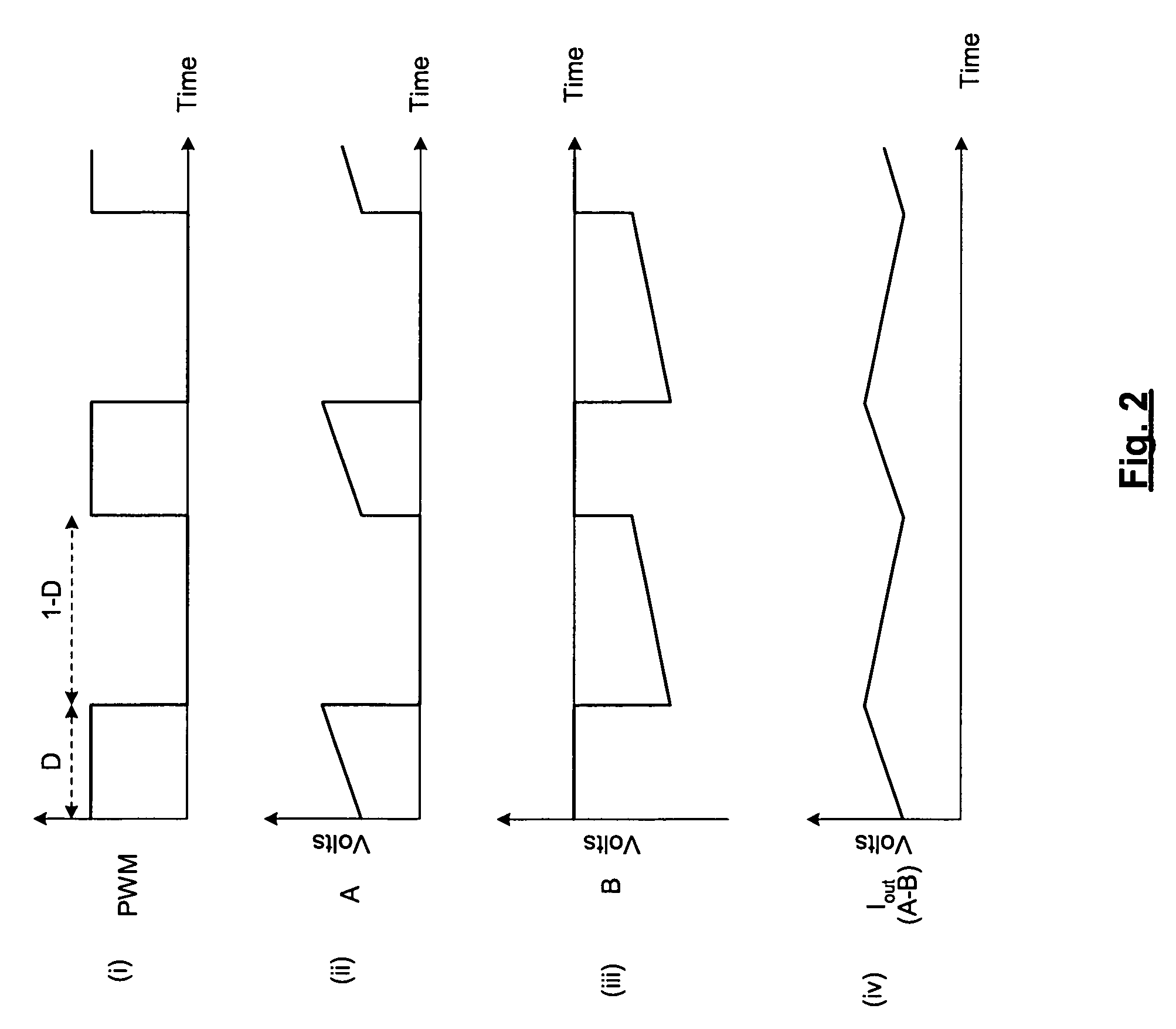
Figure 3
Abstract
Description
BACKGROUND
[0001] 1. Field of the Invention
[0002] The present invention relates generally to DC-DC power conversion.
[0003] 2. Background of the Invention
[0004] DC-to-DC power converters are power-processing circuits that convert an unregulated input DC voltage to a regulated DC output voltage. Switched-mode DC-to-DC power converters typically include an inverter, a transformer having a primary winding coupled to the inverter, a rectifying circuit coupled to a secondary winding of the transformer, and a filter connected between the rectifying circuit and the load. The inverter typically includes a pulse width modulated (PWM) switching device (i.e., the primary switch), such as a MOSFET, that converts the DC input voltage to an alternating voltage, which is magnetically coupled from the primary winding of the transformer to the secondary winding. A PWM control circuit regulates conduction of the PWM switching device. The rectifying circuit rectifies the alternating voltage on the secondary...
Examples
Embodiment Construction
[0016]FIG. 1 is a diagram of a power supply 10 according to various embodiments of the present invention and FIGS. 2(i)-(iv) are idealized voltage waveforms illustrating the operation of the power supply 10. The power supply 10 includes a DC / DC converter 12 that converts an input voltage (Vin) to an output voltage (Vout) for powering a load (not shown). The power supply 10 also includes a current limit circuit 14 and a control circuit 16. The current limit circuit 14 is for developing, according to various embodiments, a signal ( Iout) whose voltage is proportional to the average output current of the converter 12 (e.g., the current through output inductor 18). The control circuit 16 may generate a pulse width modulated control signal (PWM) based on either the output voltage or the output current of the converter 12 to control the various switches of the power supply 10, including the primary input switch 20. That is, the control circuit 16 may modulate the duty cycle (D) of the PWM...