
Submersible pump drop pipe and casing assembly connection and method of manufacture
a technology of drop pipe and casing, which is applied in the direction of hose connection, screw threaded joint, mechanical apparatus, etc., can solve the problems of not being able to run the pipes into the well, unable to properly position the coupling, and unable to achieve the effect of drilling the pipe in the well
Patent Information
- Authority / Receiving Office
- US · United States
- Patent Type
- Patents(United States)
- Current Assignee / Owner
- Publication Date
- 2007-08-28
- Estimated Expiration
- Not applicable · inactive patent
Smart Images
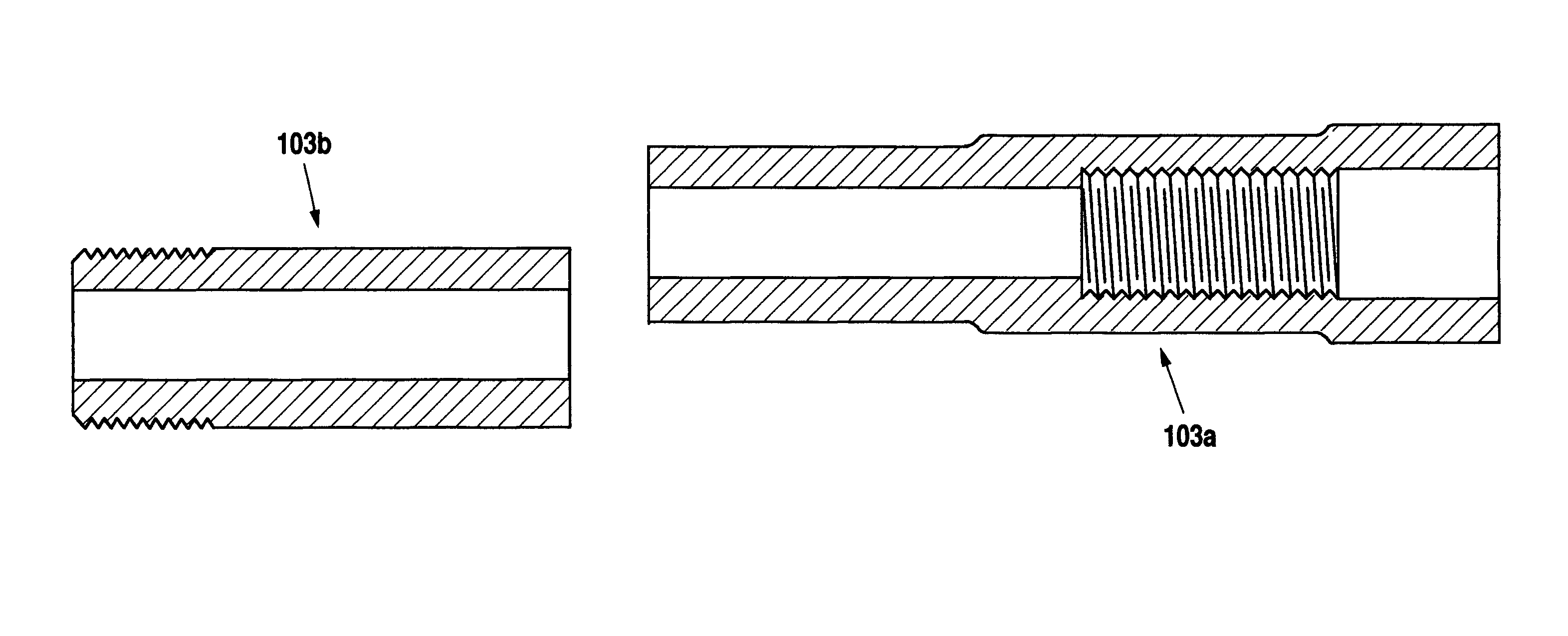
Figure 1 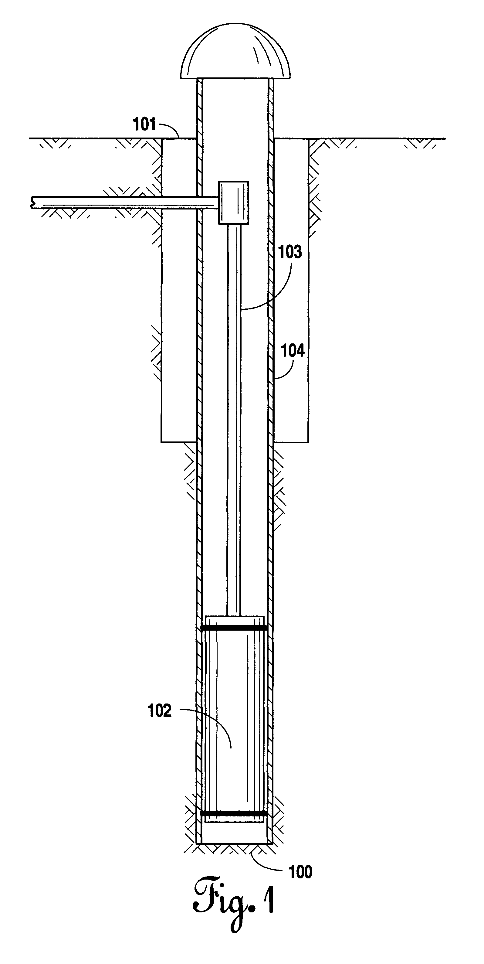
Figure 2 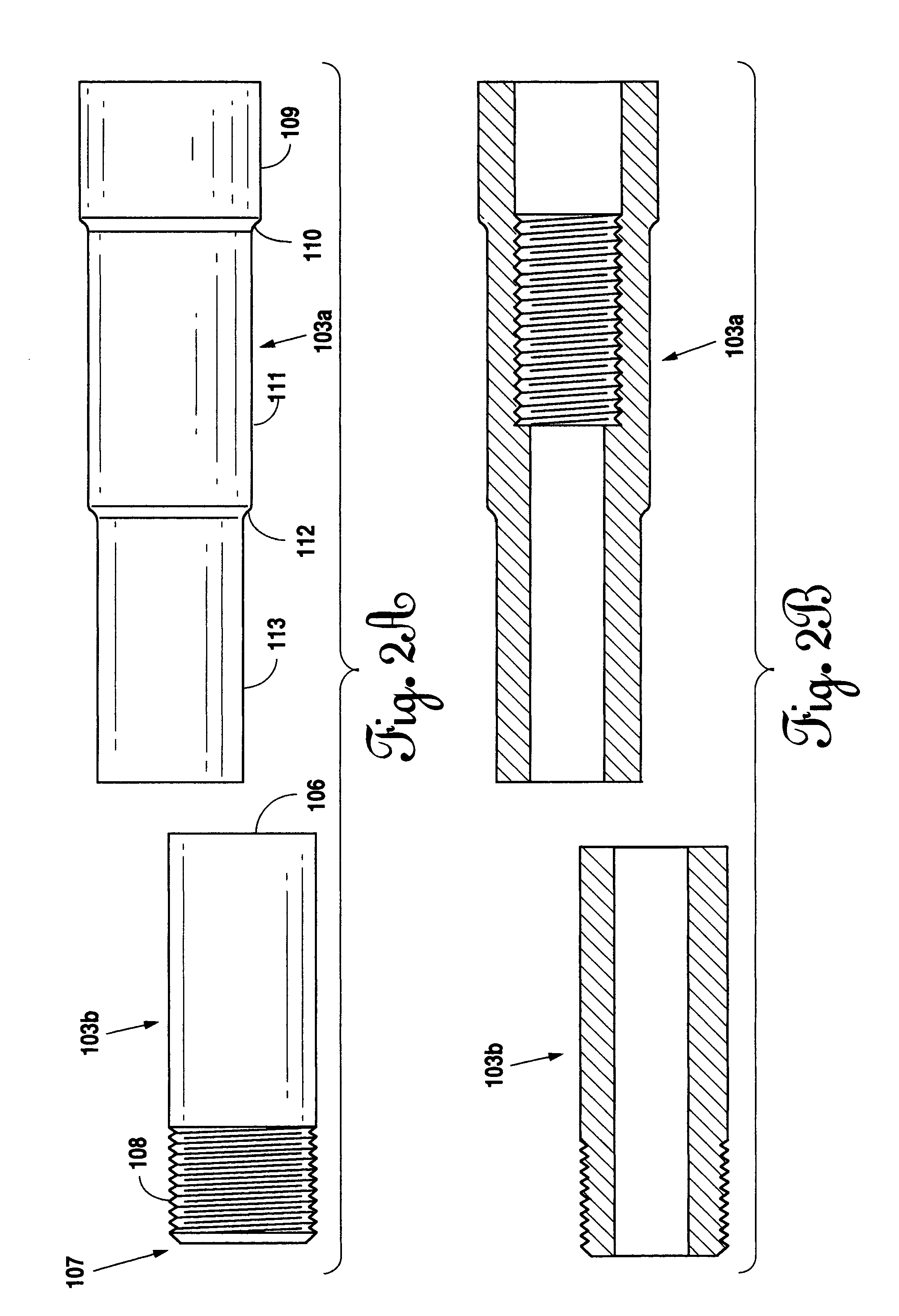
Figure 3
Abstract
Description
[0001] This application is a divisional of U.S. patent application Ser. No. 09 / 989,512 filed on Nov. 20, 2001 (now U.S. Pat. No. 6,666,480 B2).BACKGROUND OF THE INVENTION
[0002] 1. Field of the Invention
[0003] Applicant's invention relates to a submersible pump drop pipe and casing assembly connection and method of manufacture for use in water well and related systems.
[0004] 2. Background Information
[0005] In water well systems, a casing is inserted into the well to maintain the structure of the well. Within the well is placed a submersible pump to which is attached a drop pipe which carries the water from within the well to the surface. It is important in this system that the drop pipe not leak. Therefore, in modern practice pipes are joined together with couplings and sealed with large amounts of either cement or “pipe dope” to prevent leaking. The positioning of the couplings can take a great deal of effort to do properly. In addition, pipe “dope” and cement have long curing times whic...
Examples
Embodiment Construction
[0030]Referring to FIG. 1, a schematic of a typical water well where the present submersible pump drop pipe and casing could be used is illustrated. While the present invention can be useful in other obvious applications, the preferred use of the present invention is in water wells 101. The water well 101 may be drilled into an aquifer 100. The aquifer 100 is simply a water-bearing layer of sediment or rock with interconnected pore spaces or fractures that accumulate water. Upon drilling into the aquifer 100 the water well 101 is formed. Several components are inserted within the water well 101 which are necessary for its function. However, for purposes of the present invention, only certain key components will be addressed.
[0031]Within the water well 101 is placed casing 104 to keep the water well 101 open. Within the casing 104 and at the base of the water well 101 is inserted a submersible pump 102. Pump 102 is simply a motor or pump assembly that is designed to be placed entirel...