
Method and device for rotating a wafer
a technology of discs and wafers, which is applied in the direction of lighting and heating apparatus, charge manipulation, furnaces, etc., can solve the problems of complicated reactor walls, limited rotational speed, and difficulty in producing reactor walls of this nature, and achieves the effect of simple and inexpensive manner
Patent Information
- Authority / Receiving Office
- US · United States
- Patent Type
- Patents(United States)
- Current Assignee / Owner
- Publication Date
- 2008-04-01
- Estimated Expiration
- Not applicable · inactive patent
Smart Images
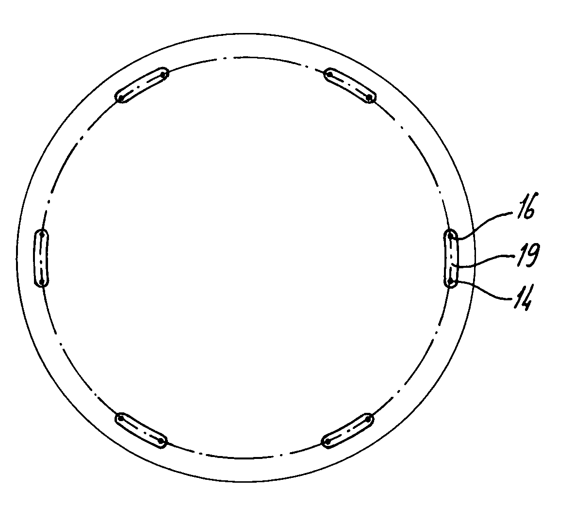
Figure 1 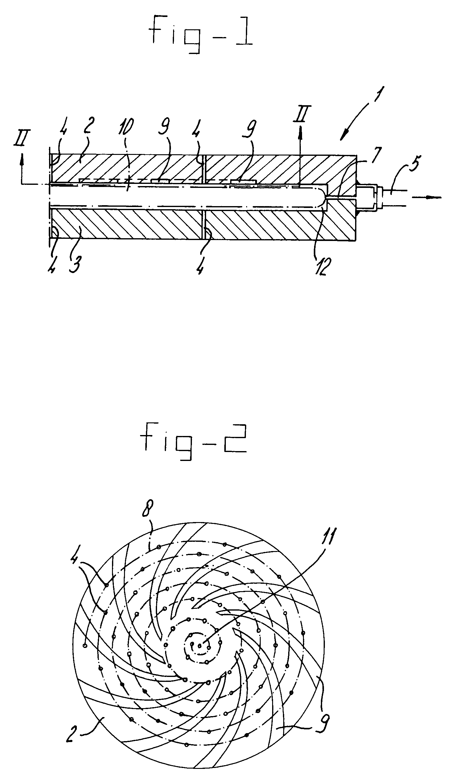
Figure 2 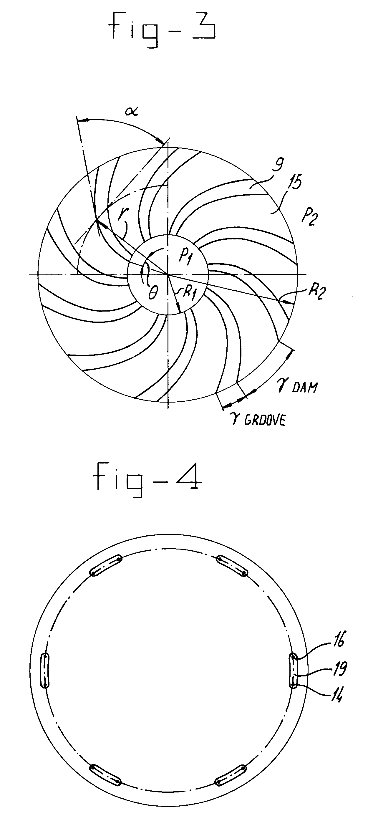
Figure 3
Abstract
Description
REFERENCE TO RELATED APPLICATION
[0001] This application is a divisional of U.S. application Ser. No. 09 / 936,257, filed Jan. 11, 2002, now U.S. Pat. No. 6,824,619, which is the U.S. national phase of International Application No. PCT / NL00 / 00154, filed Mar. 8, 2000, which claims priority from Netherlands Patent Application No. 1011487, filed Mar. 8, 1999.FIELD OF THE INVENTION
[0002] The present invention relates to a method for rotating a disc-shaped object, such as a wafer, wherein along a side of said object a gas flow is directed, giving a rotation to said object, wherein said gas flow is given the rotation generating component being tangential to said object by a pattern of grooves.BACKGROUND OF THE INVENTION
[0003] Such a method is known from U.S. Pat. No. 3,706,475. In this specification a device is disclosed for transporting wafers. The device comprises an elongated trajectory and from the lower side gas is added in such a way that except from a transferring movement also a rotatin...
Examples
Embodiment Construction
[0023]In FIG. 1, a reactor is denoted overall by 1. This reactor is shown only in part and comprises a top part 2 and bottom part 3. In any desired way, which is not illustrated, a wafer 10 may be accommodated in the chamber or treatment space 12 delimited between these parts 2 and 3. The treatment gas for the wafer is introduced via gas-introduction openings 4 both above and below the wafer, and this wafer then adopts a floating position. Gas is discharged via discharge openings 7 which may be of any conceivable form and emerge at a circumferential channel 6 which is connected to a discharge line 5.
[0024]In order to impart rotation to the wafer, the top part, as can be seen from FIGS. 1 and 2, is provided with a number of grooves 9. These grooves 9 are spiral-shaped, and the origin of the spiral lies in the vicinity of the aimed centre 11 of the wafer 10. The end of the spiral is situated in the vicinity of the circumferential edge of the wafer. Grooves 9 with the shape of a logari...