
Bandpass filter and wireless communications equipment using same
a wireless communication and filter technology, applied in the field of bandpass filters, can solve the problems of dielectric filters failing to have a wide passband and small size at the same time, extending the bandwidth to be used as bandpass filters for wider frequency bands, and affecting the signal receiving sensitivity, so as to achieve wide passband communication, improve signal receiving sensitivity, and simple structur
Patent Information
- Authority / Receiving Office
- US · United States
- Patent Type
- Patents(United States)
- Current Assignee / Owner
- Publication Date
- 2008-12-23
- Estimated Expiration
- Not applicable · inactive patent
Smart Images
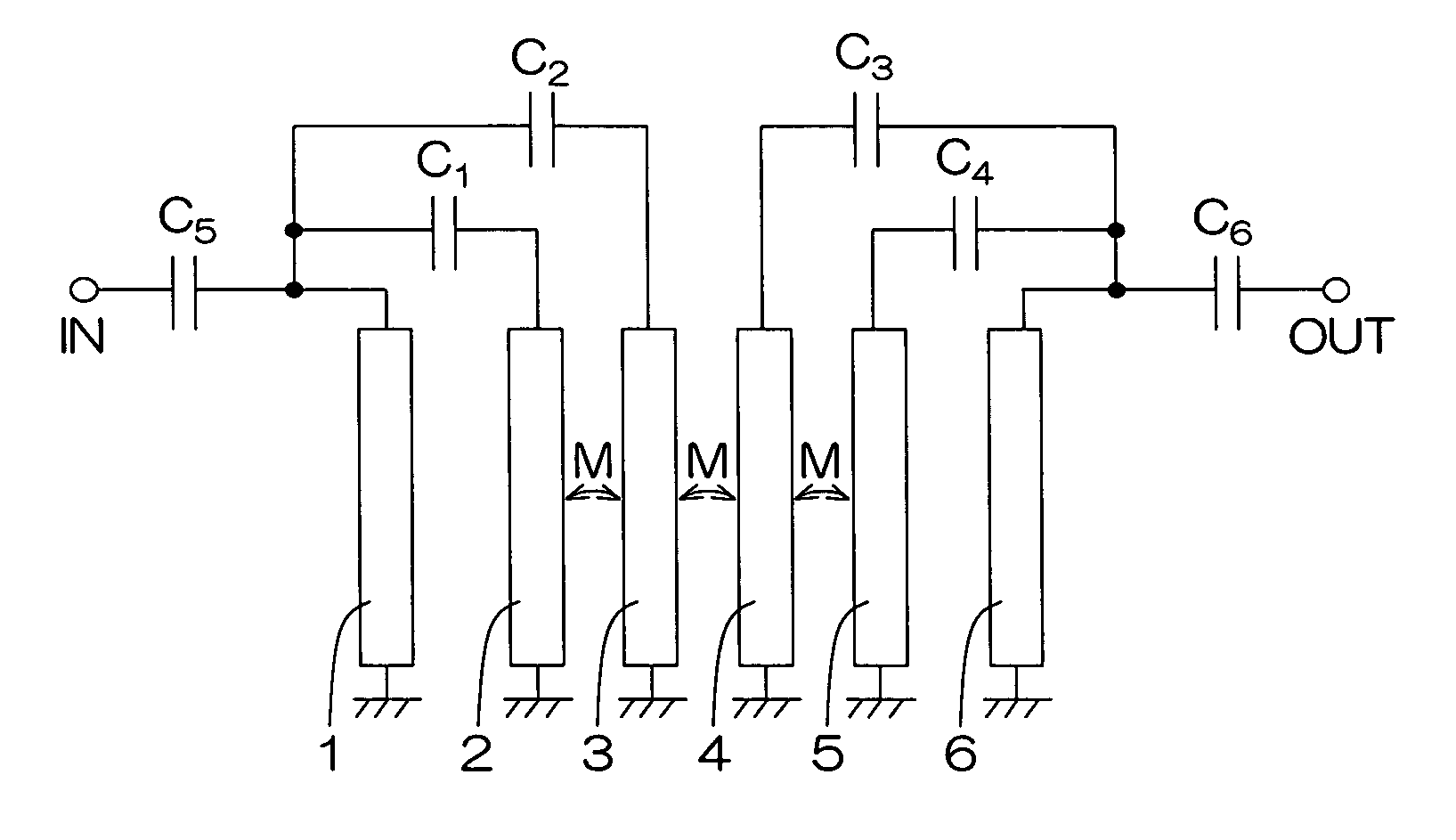
Figure 1 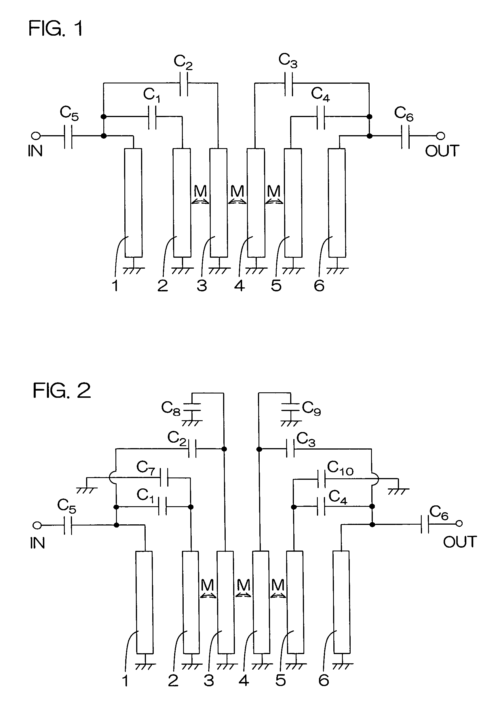
Figure 2 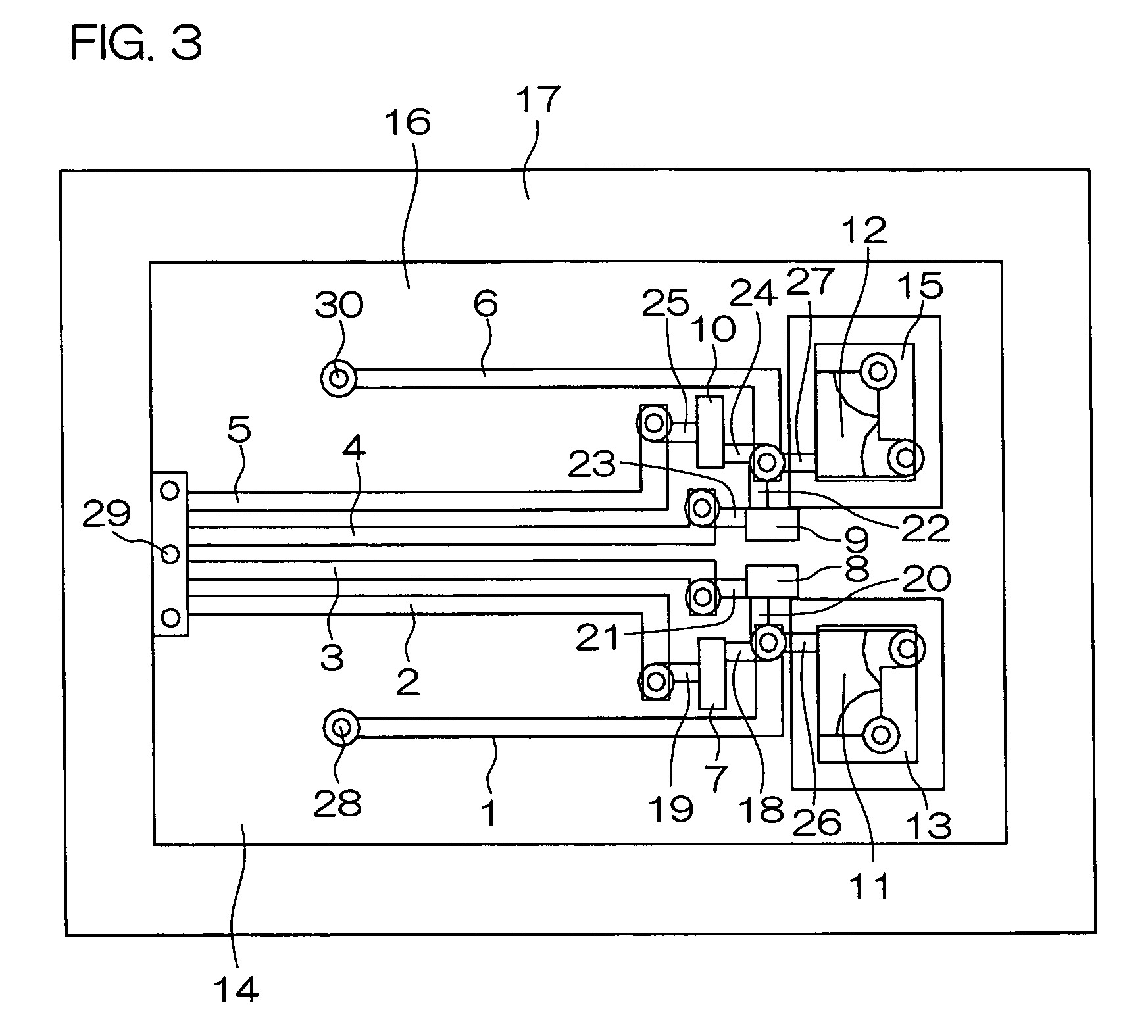
Figure 3
Abstract
Description
BACKGROUND OF THE INVENTION
[0001] 1. Field of the Invention
[0002] The present invention relates to a bandpass filter with wide bandpass characteristics and steep attenuation characteristics which is used suitably for UWB (Ultra Wide Band) in the wireless communications field, and communications equipment using the bandpass filter. UWB is expected to be utilized as a data transmitting medium for PC peripheral equipment such as external storage devices, printers and scanners, or as a data communications medium for digital TVs, projectors, digital steel cameras, digital video cameras, etc.
[0003] 2. Description of the Related Art
[0004] In recent years, attention is being given to UWB as a means of communications. This UWB is different from wireless local area network (herein after referred to as “W-LAN”) in communication length and data transmission rate.
[0005] According to IEEE802.11.b, one of the standards for W-LAN, the communication length is 30-100 m, transmission power is 500 mW and tr...
Examples
example
[0168]A bandpass characteristic S21 and a reflection characteristic S11 of a bandpass filter fabricated with wiring patterns shown in FIGS. 4A-4H and FIGS. 5A-5E were measured using the vector network analyzer 8719ES produced by Agilent Technologies.
[0169]In this case, ceramics with a dielectric coefficient of 9.0 was used, and the dielectric layers consisted of twelve layers and the thickness of each of the dielectric layers was 75 um. The size of the dielectric was 4.5×3.2 mm. The measured bandpass characteristic S21 and reflection characteristic S11 are shown as a graph in FIG. 10.
[0170]In addition, with the conditions being the same, a bandpass characteristic S21 and a reflection characteristic S11 of a bandpass filter additionally comprising a conductor pattern 99 shown in FIGS. 8A-8E, in which the input terminal electrode and output terminal electrode were connected through an input / output capacitance C11 were measured. The results of this are shown in FIG. 11.
[0171]According ...