
Brake disk
a technology of brake discs and cylinders, applied in the direction of brake discs, braking elements, brake types, etc., can solve the problems of large difference in mass between the friction surface and the extension, the connection of components can bend, and the friction surface can be detached from its seat, so as to improve the entry of air, improve the effect of airflow and reduce the tendency to crack formation of these components
Patent Information
- Authority / Receiving Office
- US · United States
- Patent Type
- Patents(United States)
- Current Assignee / Owner
- Publication Date
- 2013-08-20
- Estimated Expiration
- Not applicable · inactive patent
Smart Images

Figure 1 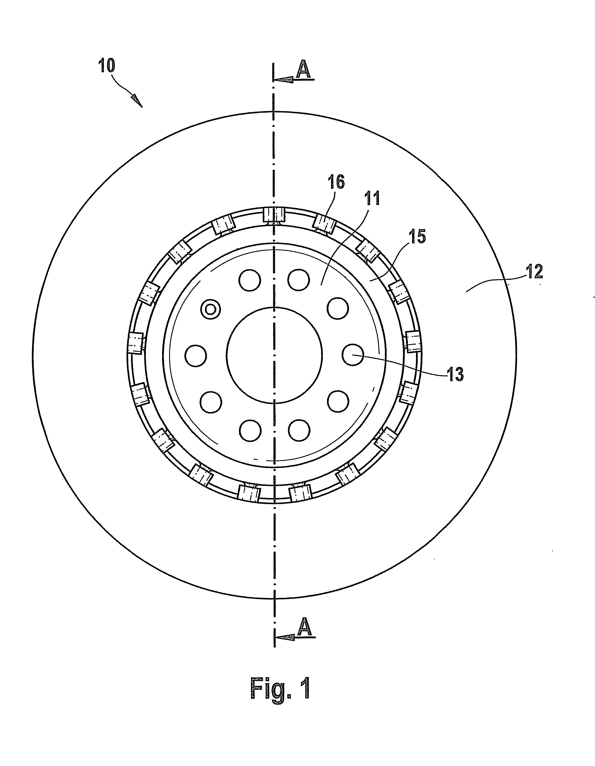
Figure 2 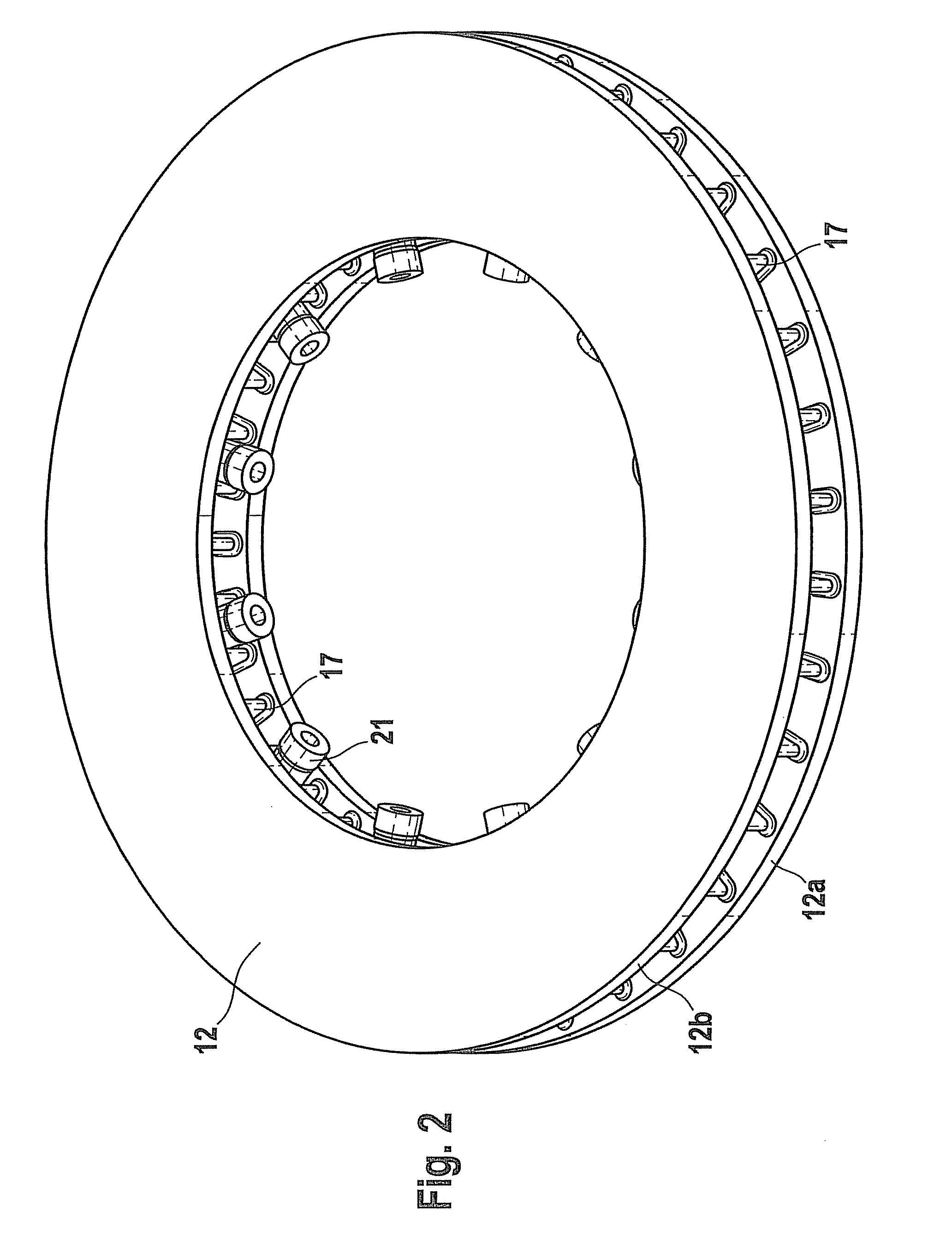
Figure 3
Abstract
Description
FIELD OF THE INVENTION
[0001] The present invention relates to a brake disk, in particular a ventilated brake disk, having a friction ring and a bearer part, in particular a disk pot, connected to a friction ring via connecting elements.BACKGROUND INFORMATION
[0002] German Patent No. DE 43 32 951 A1 describes a ventilated brake disk that has a friction ring and a bearer part connected to the friction ring by connecting elements. The connecting elements are fashioned in particular as pins, bolts, or the like, and are distributed around the circumference of the bearer part. The connecting elements extend into openings in the circumferential wall of the friction ring. In this way, the friction ring is mounted in “floating” fashion on the disk pot. Here, when there is a rise in temperature caused by the braking process, the connecting elements can expand in the radial direction without danger of warping. However, given larger torques there is the danger that, due to the free length of the c...
Examples
Embodiment Construction
[0009]In FIG. 1, reference character 10 designates a brake disk made up of a disk pot 11 and a friction ring 12. In a conventional manner, disk pot 11 is fastened (in a manner not shown here) on a hub of a vehicle, the fastening screws extending through bores 13 of disk pot 11. Disk pot 11 is connected to friction ring 12 (as is shown in more detail in FIGS. 2 and 3) via a large number of connecting elements 16 formed in circumferential wall 15 of disk pot 11, in the form of pins or bolts or the like. Friction ring 12 is made up of two friction rings 12a and 12b, which are connected to one another by a large number of webs 17 distributed over the circumference, and in particular running in the radial direction, so that a ventilated brake disk results. As can be seen in more detail in FIG. 2 and FIG. 3, bearer webs 18 that run radially are situated on two successive webs 17. Here, bearer webs 18 are situated segment by segment, so that in each case a free web 17 is situated between s...