
Test blade
a technology of blades and blades, applied in the field of test blades, can solve the problems of blades affecting the trailing blade and the surrounding engine casing at high speed, blades becoming detached from the hub, affecting the trailing blade and the surrounding engine casing, etc., and achieve the effect of reducing delamination
Patent Information
- Authority / Receiving Office
- US · United States
- Patent Type
- Patents(United States)
- Current Assignee / Owner
- Publication Date
- 2017-12-05
Smart Images
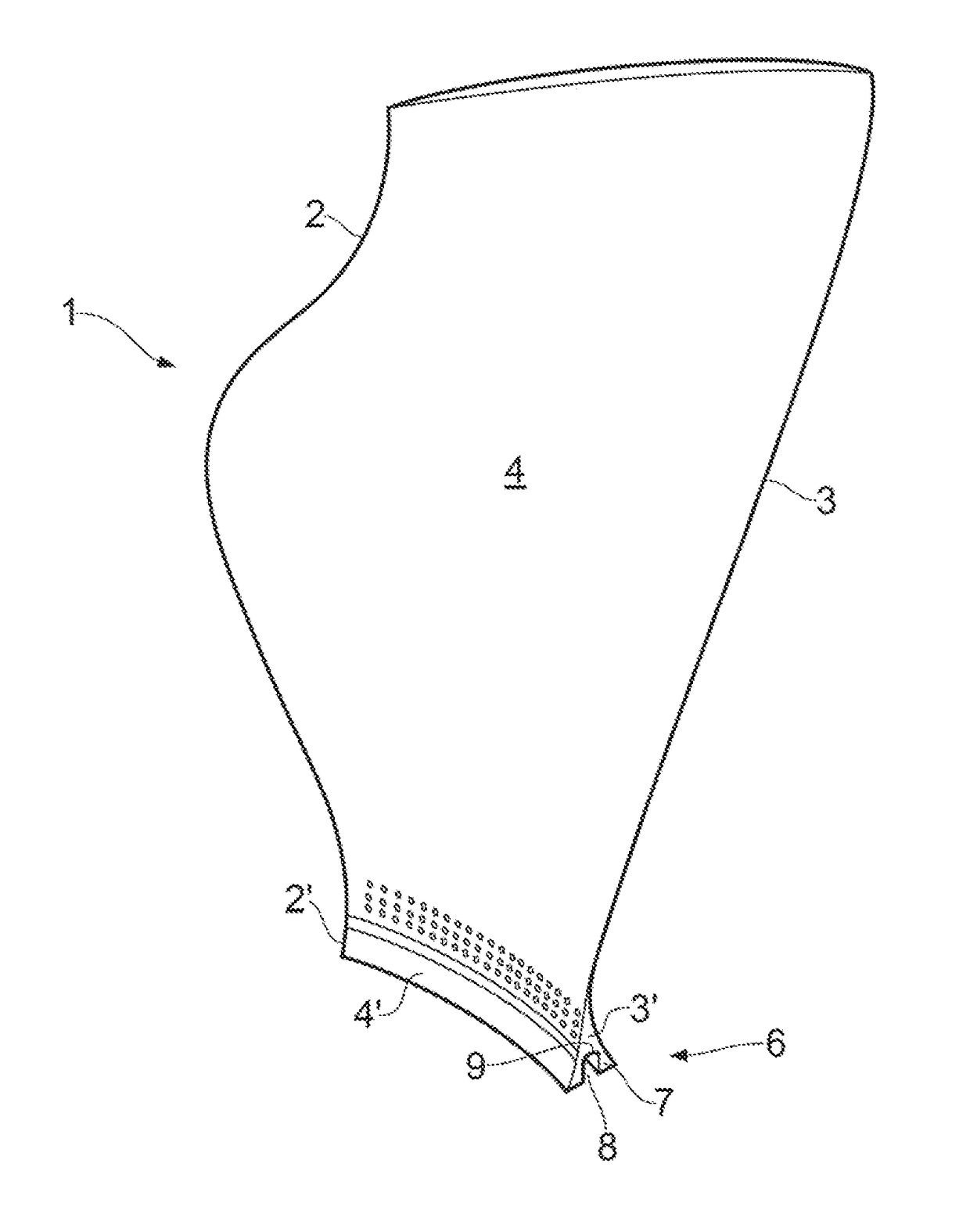
Figure 1 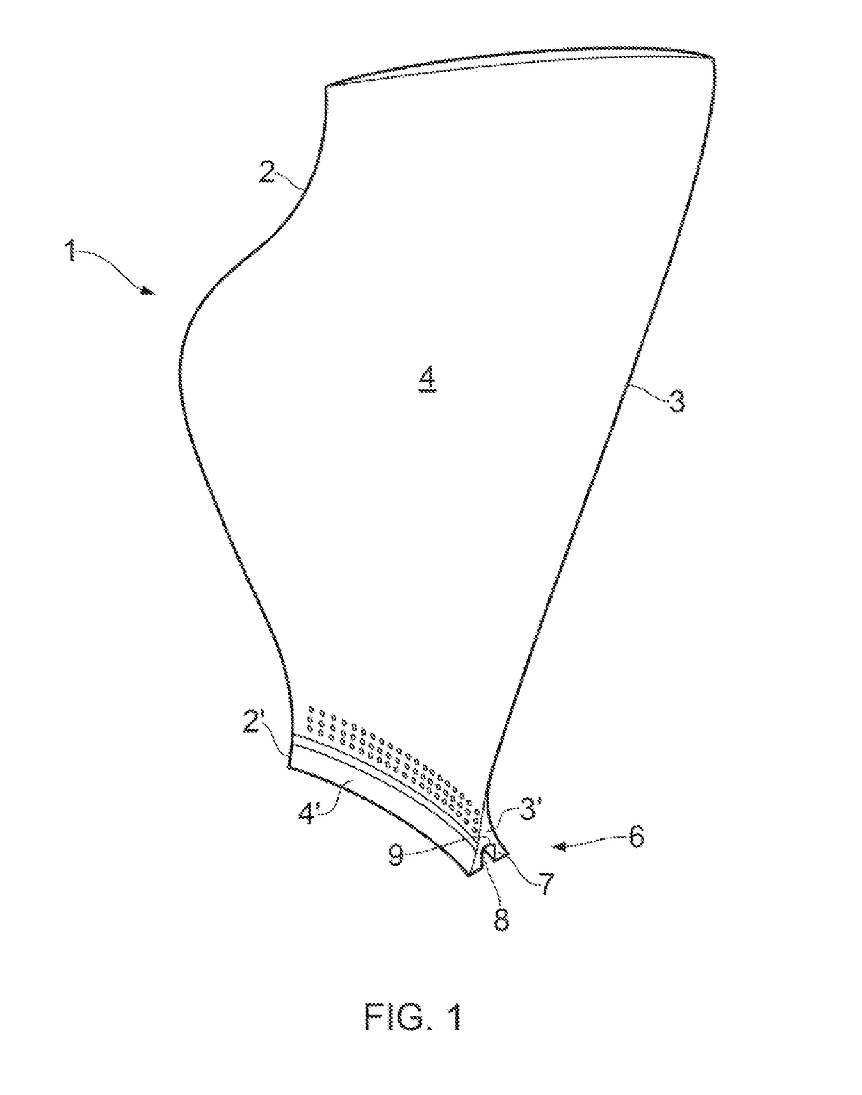
Figure 2 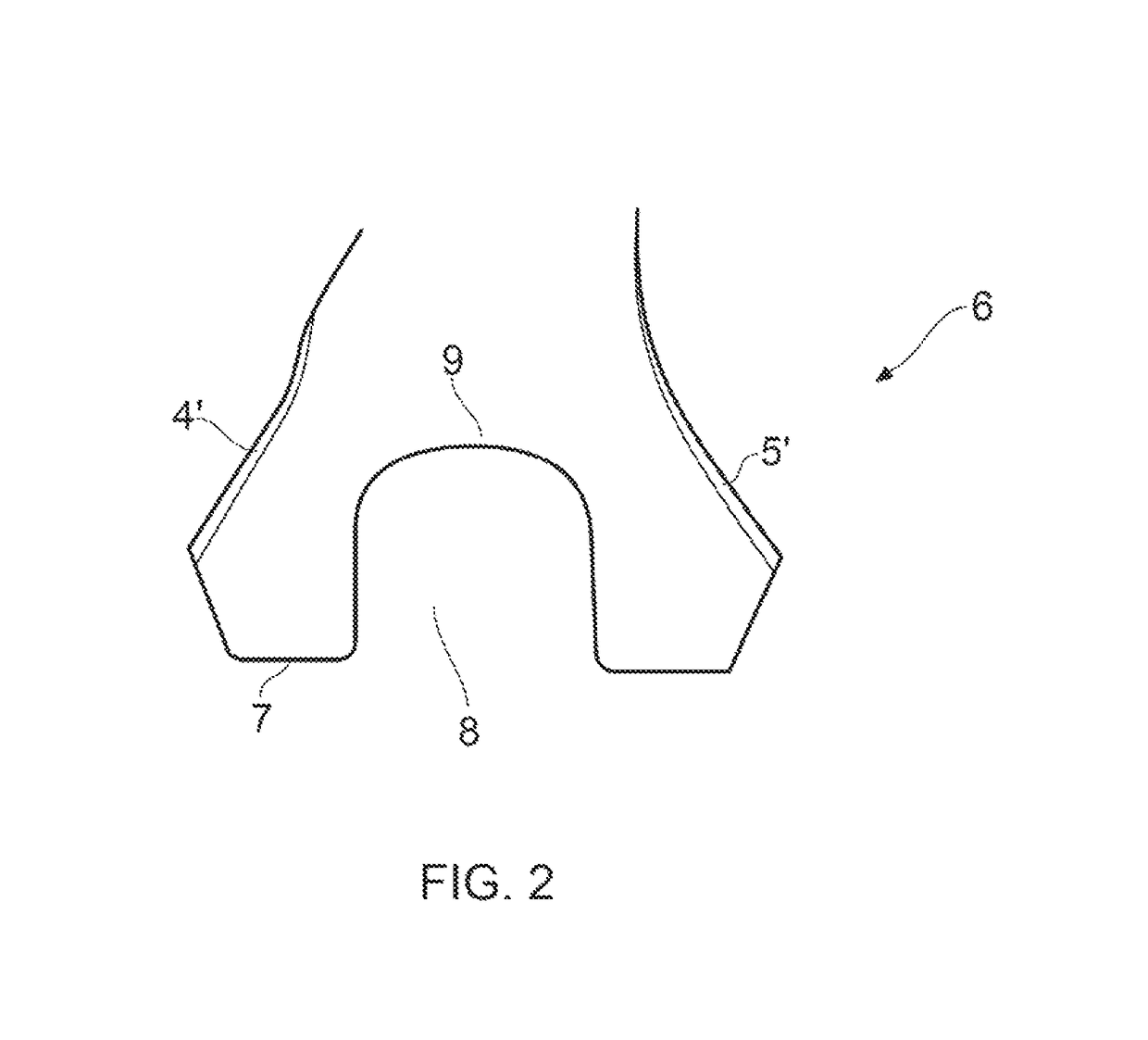
Figure 3
Abstract
Description
FIELD OF THE INVENTION
[0001] The present invention relates to a test blade and / or to a method of preparing a test blade and is concerned particularly, but not exclusively, with a fan blade modified for an explosive release test, and / or to a method for preparing such a blade.BACKGROUND
[0002] A gas turbine jet engine includes a number of sets of blades that are mounted on rotational hubs. These include fan blades, turbine blades and compressor blades, all of which rotate at high speed. In use, it is possible, although extremely unlikely, for a blade or part of a blade to become detached from the hub on which it is mounted whilst rotating. This results in the blade impacting its trailing blade and surrounding engine casing at high speed. Due to the mass and speed of the blade, the force at which impact occurs can be very high. It is therefore important that any damage caused by such an impact is not critical. Tests are therefore carried out to evaluate the damage which would be caused by...
Examples
first embodiment
[0070]a test blade 1 is shown in FIGS. 1 and 2.
[0071]The blade 1 comprises a radially extending leading edge 2 and trailing edge 3 axially spaced by a (concave) pressure surface 4 and a circumferentially opposed (convex) suction surface 5. The camber line extends from the leading edge 2 to the trailing edge 3 of the blade 1 midway between the pressure and suctions surfaces 4, 5 of the blade 1.
[0072]The blade 1 has a root portion 6 for mounting on a rotatable hub 10 (shown in FIG. 3).
[0073]The root portion 6 comprises a radially inner surface 7 having a channel 8 extending along the entire length of the camber line of the radially inner surface 7 to the leading edge 2′ and the trailing edge 3′ of the root portion 6.
[0074]By providing a channel on the radially inner surface 7 of the root portion 6, the ease of manufacture of the test blade 1 is improved because it is much easier to machine a channel 8 into the surface of the root portion than drill bores into the root portion 6. This ...
second embodiment
[0091]In the second embodiment shown in FIGS. 7 and 8, the root portion 6 further comprises axially extending slots 22 extending from both the leading and trailing edges 2′, 3′ on both the suction surface 5′ and pressure surface 4′ of the root portion 6.
[0092]Each axially extending slot 22 extends through the root portion 6 in the thickness (circumferential) direction (from the pressure surface 4′ or the suction surface 5′ of the root portion 6) to join the channel 8.
[0093]The axial slots 22 in the second embodiment are to provide areas of radial weakness at the axially outer ends of the channel which is where, in use, the detonators are positioned. The force of the explosion is reduced in these areas (by the absence of explosive charge) and the slots are provided to ensure cleaving of the blade from the root portion in these areas especially in static tests (where no centrifugal force is applied to the test blade).