Operation equipment for LED

A technology of light-emitting diodes and circuit devices, applied in the field of circuit devices, can solve the problems of electromagnetic incompatibility radio, interference, high cost of filtering and shielding forms, etc., and achieve the effect of reducing electromagnetic interference and reducing the amplitude.

Inactive Publication Date: 2009-04-01
PATENT TREUHAND GESELLSCHAFT FUR ELECTRIC GLUEHLAMPEN MBH
View PDF5 Cites 0 Cited by
  • Summary
  • Abstract
  • Description
  • Claims
  • Application Information

AI Technical Summary

Problems solved by technology

This can lead to electromagnetic incompatibility or radio interference, especially in the case of long connecting lines
In order to prevent this and to comply with the relevant norms (eg CISPR 15), high costs in the form of filtering and shielding are often required

Method used


Image

  • Operation equipment for LED
  • Operation equipment for LED
  • Operation equipment for LED

Examples


Embodiment Construction

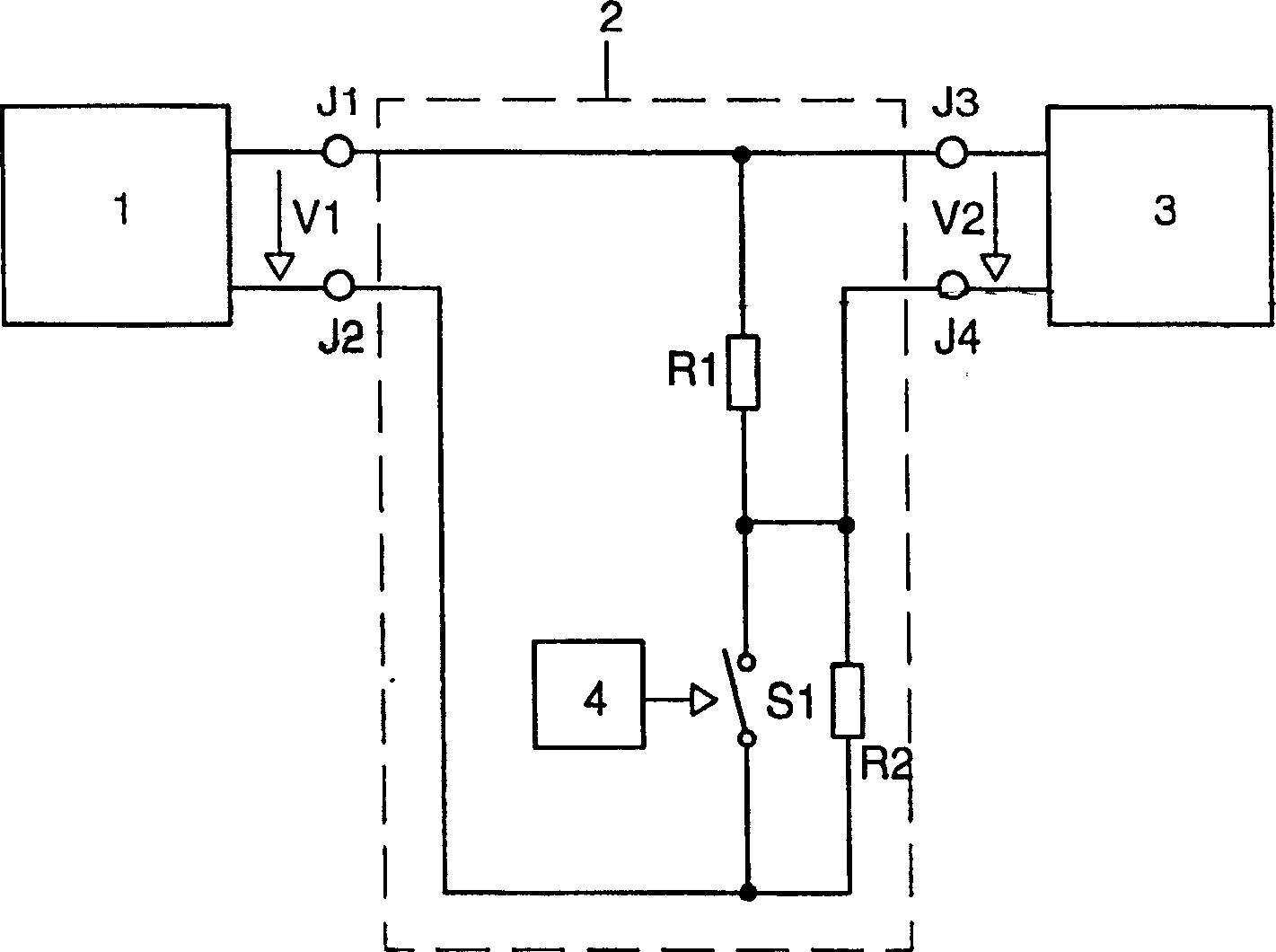
[0023] Attached figure 1 A block circuit diagram of the circuit arrangement of the present invention for operating the LED is shown in. The electronic converter 1 provides the power supply voltage V1 to the dimming module 2 at the connection points J1 and J2. The dimming module 2 provides the output voltage V2 to the LED 3 at the connection points J3 and J4. Through the connection from the connection point J1 to the connection point J2 in the dimming module 2, a section of the first connection wire leading from the electronic converter 1 to the LED 3 is formed. A section of the second connecting wire leading from the electronic converter 1 to the LED 3 is led from the connection point J22 to the connection point J4 through the electronic switch S1 in the dimming module. The control circuit 4 controls the electronic switch S1 as follows, so that the LED 3 operates in a pulsed operation mode. According to the present invention, a pull-down resistor R2 is connected parallel to the e...


PUM


Abstract

The present invention provides a circuit having an electronic switch for the LED operating current, characterized in that the device has a pull-down device in parallel with the electronic switch, the resistance of the pull-down device is dimensioned so that the ratio of the operating current with the switch closed to the operating current with the switch open is described by a reduction factor of at least 10. Thus the electromagnetic interference of the circuit device is reduced.

Description

Technical field [0001] The invention relates to a circuit arrangement for operating a light-emitting diode with an operating current that basically flows through an electronic switch. This relates in particular to an electronic operating device for operating light-emitting diodes, the operating device containing a device for adjusting the effective value of the operating current of the light-emitting diode, wherein this device has a pulsed operating mode. Background technique [0002] In order to operate light-emitting diodes, hereinafter referred to as LEDs, the following circuit devices have been promoted: a power source such as a public grid or a storage battery supplies power to an electronic converter that provides the power supply voltage. The LED is usually connected to the power supply voltage via two connecting wires. One or more LEDs can be operated on one supply voltage. Multiple LEDs are usually connected in series and form a so-called shunt. Multiple shunts can be co...

Claims


Application Information

Patent Timeline
Patent Type & Authority Patents(China)
IPC IPC(8): H05B37/02H05B44/00
CPCH05B33/0818H05B45/3725
Inventor U·弗兰切斯库蒂G·希拉
Owner PATENT TREUHAND GESELLSCHAFT FUR ELECTRIC GLUEHLAMPEN MBH
Why Eureka
Try Eureka