Two-section lens driver

A lens driving device, two-stage technology, applied in installation, optics, instruments, etc., can solve problems such as undisclosed technical features

Inactive Publication Date: 2007-10-03
POWERGATE OPTICAL INC
View PDF4 Cites 4 Cited by
  • Summary
  • Abstract
  • Description
  • Claims
  • Application Information

AI Technical Summary

Problems solved by technology

[0005] Although U.S. Patents US 5,150,260, US 6,392,827, US 5,220,461 and US 5,471,100 have disclosed prior art of seve...

Method used


Image

  • Two-section lens driver
  • Two-section lens driver
  • Two-section lens driver

Examples


Embodiment Construction

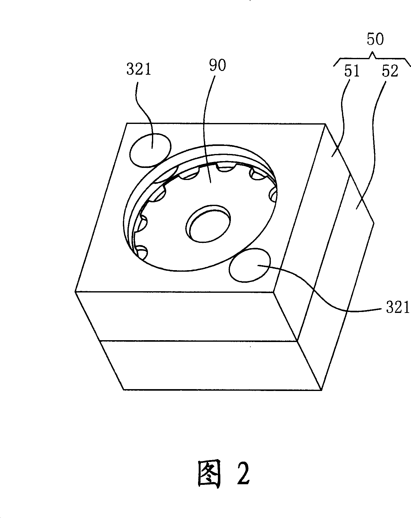
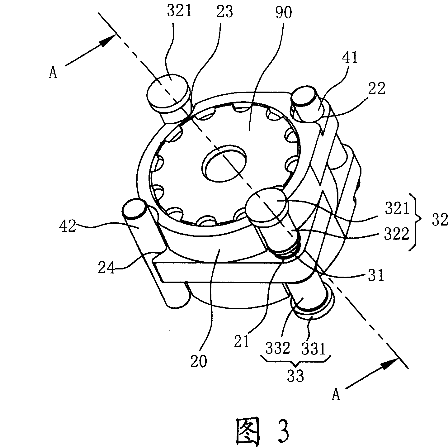
[0032]Please refer to FIG. 2 to FIG. 4B , which disclose a first preferred embodiment of the two-stage lens driving device of the present invention. Wherein, FIG. 2 is a three-dimensional combined view of the first preferred embodiment of the two-stage lens driving device of the present invention. FIG. 3 is a three-dimensional assembly view of the first preferred embodiment of the two-stage lens driving device of the present invention after the housing is removed. 4A is an A-A cross-sectional view of the two-stage lens driving device of the present invention as shown in FIG. 2 , when the lens carrying seat is in the first position. 4B is an A-A cross-sectional view of the two-stage lens driving device of the present invention as shown in FIG. 2 , when the lens carrying seat is in the second position.

[0033] As shown in Fig. 2, Fig. 3, Fig. 4A and Fig. 4B, in the first preferred embodiment of the present invention, the two-stage lens driving device includes: a A lens holder...


PUM


Abstract

The two-section lens driver includes one lens bearing seat, one guide mechanism, one electromagnetic driving mechanism, and one casing. The guide mechanism combined to the bearing seat guides the bearing seat to displace linearly in an axial direction. The electromagnetic driving mechanism includes at least one magnetically inducing assembly fixed on the bearing seat, and at least one first coil assembly and at least one second coil assembly set coaxially on two ends of the magnetically inducing assembly separately. When some current is applied to one of the coil assemblies, one magnetic force is generated to make the magnetically inducing assembly move between these two coil assemblies.

Description

technical field [0001] The invention relates to a two-stage lens drive device, in particular to a lens drive device which uses an electromagnetic drive device as a power source to drive a lens carrying seat to perform two-stage position switching motion. Background technique [0002] Please refer to FIG. 1 , in a general photographing device 1 , it is composed of a lens group 11 and a light sensing component 12 . The lens group 11 can image the reflected image light of the subject on the light sensing component 12 . Because if the distance between the lens group 11 and the light sensing component 12 is fixed (that is, a fixed-focus lens), it can only clearly present objects at a distance of 2-3 meters (Hyperfocal Distance). If you want to have a close-up function, you must use an additional lens driving device to drive the lens group to move, so as to change the distance between the lens group and the light sensing component to achieve the purpose of focusing (Focus). [0...

Claims


Application Information

Patent Timeline
IPC IPC(8): G02B7/10G02B7/04
Inventor 何文仁张吉龙杨新成游桓一
Owner POWERGATE OPTICAL INC
Why Eureka
Try Eureka