
Tyre expanding mechanism for X-ray tyre detecting machine
A detection machine and X-ray technology, which is applied to measurement devices, use of wave/particle radiation, material analysis using radiation, etc., can solve the difficulty of increasing the accuracy of control of the operating position of the tire support shaft, the complex structure, and the unstable operation. and other problems, to achieve the effect of simplified structure, stable operation and accurate operation
Patent Information
- Authority / Receiving Office
- CN · China
- Patent Type
- Applications(China)
- Current Assignee / Owner
- Publication Date
- 2009-02-11
Smart Images
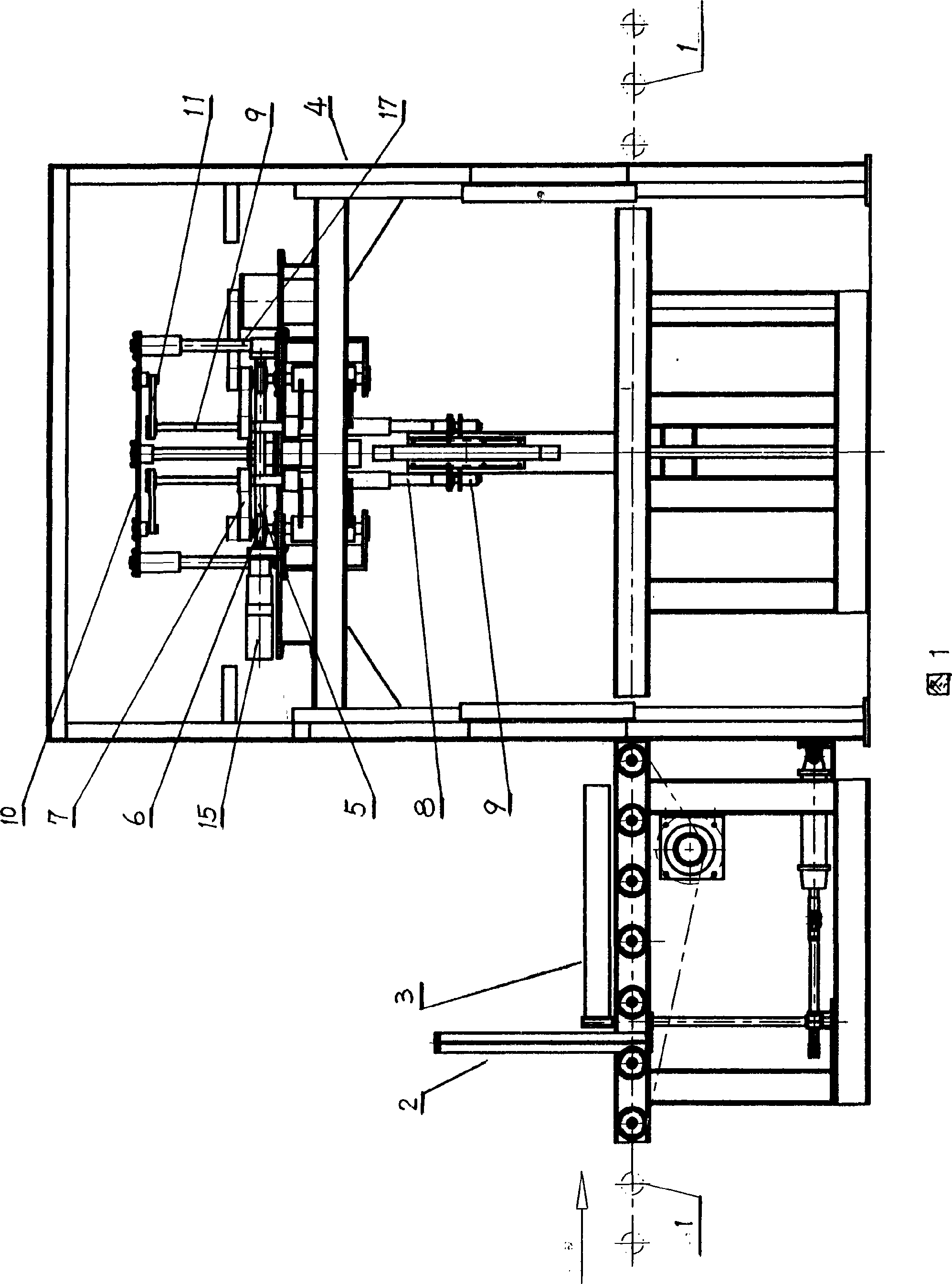
Figure 1 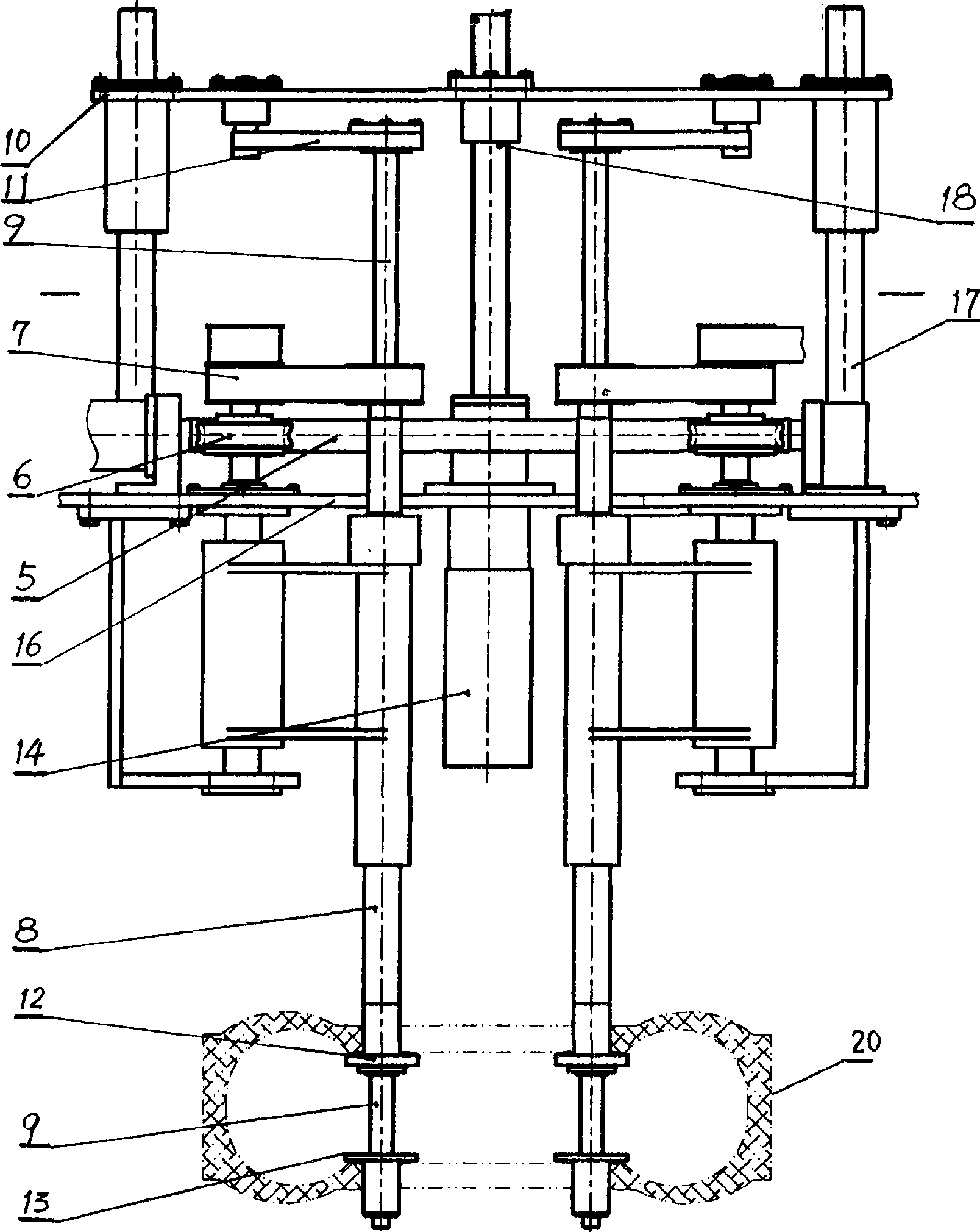
Figure 2 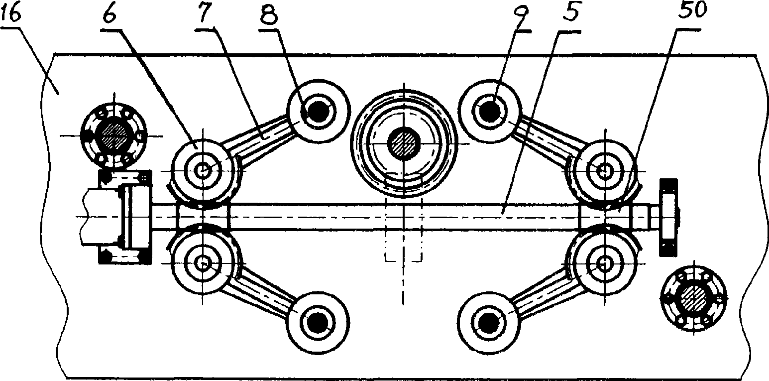
Figure 3
Abstract
Description
technical field
[0001] The invention relates to a tire expanding mechanism in an X-ray tire testing machine. Background technique
[0002] The X-ray tire inspection machine mainly includes a tire transmission part, a tire specification measurement part, a tire expansion mechanism part and an X-ray and imaging system part. The tire is brought into the detection area of the X-ray and imaging system along the tire transmission part. The mechanism part implements the operation of stretching and expanding the tire so that the X-ray tube enters the inner space of the tire for imaging detection. The existing tire support and expansion mechanisms all use four tire support shafts and two tire expansion heads for each tire support shaft to complete tire positioning and edge opening operations on both sides, so the design core of the tire support and expansion mechanism is to require four tire support The axes always run synchronously on the same circle center. The more common supp...
Examples
Embodiment Construction
[0007] Figure 1 and figure 2 As shown, the X-ray tire inspection machine mainly includes a tire transmission part 1, a tire specification measurement part 2, a tire centering part 3, a tire expansion mechanism part 4, and an X-ray and imaging system part. In the figure, the X-ray and imaging system Some parts are omitted to fully demonstrate the tire expansion mechanism of this support. The X-ray tire inspection machine of the present invention supports the tire expansion mechanism, and the specific implementation structure of its main body is as follows: image 3 As shown, the mechanism is two sets of symmetrical worm and gear transmission parts driven coaxially. Two worm gears 6 are arranged symmetrically on both sides of the two worms 50, and the tire support arm 7 and the worm gear 6 assembled with the tire support shaft 8 are fixedly arranged and formed on the worm 50, which is also a tire support part symmetrical to the center line of the axis 5. Figure 1, figure 2 As...