

Vehicle interior illumination lamp unit
An indoor lighting and vehicle technology, which is applied to vehicle interior lighting devices, signal devices, vehicle components, etc., can solve problems such as scattering, warping of the latched part, and the falling of the design part, and achieves prevention of light leakage, detachment, and omission. The effect of using a ground wire
- Summary
- Abstract
- Description
- Claims
- Application Information
AI Technical Summary
Problems solved by technology
Method used
Image

Examples
Embodiment 1
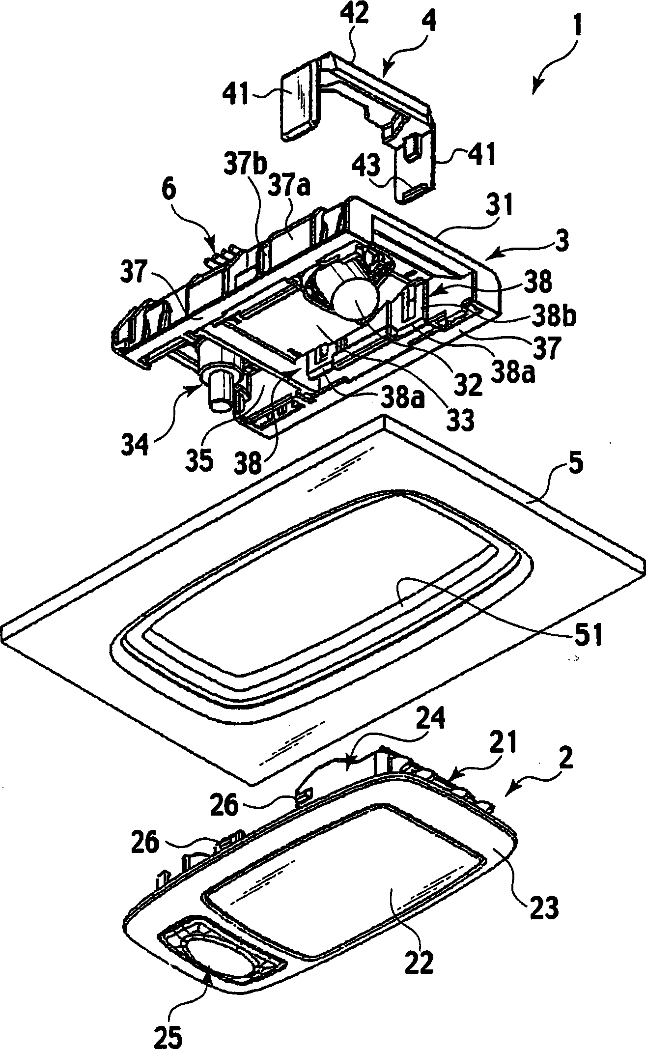
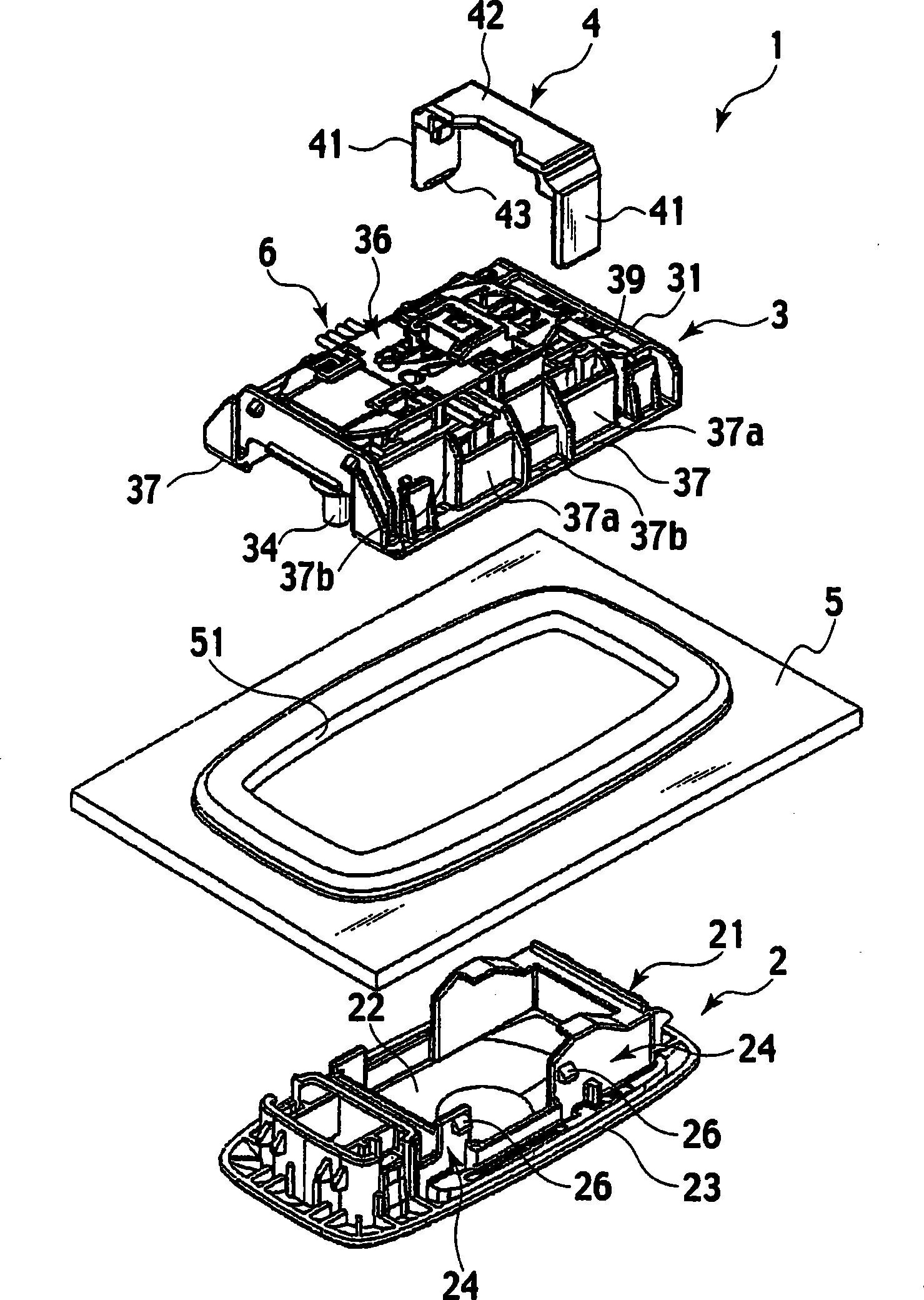
[0047] Such as figure 1 and figure 2 As shown, the vehicle-mounted interior lighting device 1 of the first embodiment roughly includes a design part 2 , a function part 3 , and a positioning part 4 . The design part 2 is provided on the lower side of the roof panel 5 forming the roof of the vehicle. Furthermore, the functional part 3 is provided on the upper side of the ceiling panel 5 . By combining the design portion 2 and the function portion 3 , the ceiling panel 5 is sandwiched by these design portion 2 and function portion 3 . In order to combine these design parts 2 and function parts 3 , a substantially rectangular mounting hole 51 is provided in the ceiling panel 5 .
[0048] The design part 2 includes a base case 21 , and a transparent or translucent lens cover 22 detachably provided on the lower side of the base case 21 . The base case 21 includes a rectangular frame plate portion 23 exposed on the interior side of the vehicle, and a protruding portion 24 forme...
Embodiment 2
[0069] Figure 8 ~ Figure 15 Represents Example 2 of the present invention.
[0070] When the vehicle-mounted interior lighting device 1A of the second embodiment is compared with the vehicle-mounted interior lighting device 1 of the above-mentioned embodiment 1, as follows: Figure 8 ~ Figure 11 As shown, in the vehicle-mounted interior lighting device 1A, the structure of the positioning part 4A is different, and the circuit of the functional part 3 is provided with a grounding channel.
[0071] Such as Figure 12 and Figure 13 As shown, the positioning portion 4A is formed of conductive material. The positioning portion 4A is a substantially U-shaped member. The positioning portion 4A is integrally provided with a pair of insertion plate portions 41A having a drop-off preventing engagement portion 43A at the end, a connecting plate portion 42A connecting them, and a pair of mounting plate portions 44A extending outward from the connecting plate portions 42A. Screw ins...
Embodiment 3
[0084] Figure 16 ~ Figure 2 2 represents Example 3 of the present invention.
[0085] Such as Figure 16 ~ Figure 2 As shown in 0, the vehicle-mounted interior lighting device 1B of the third embodiment is different from the vehicle-mounted interior lighting device 1 of the first embodiment only in the configuration of the positioning unit 4B.
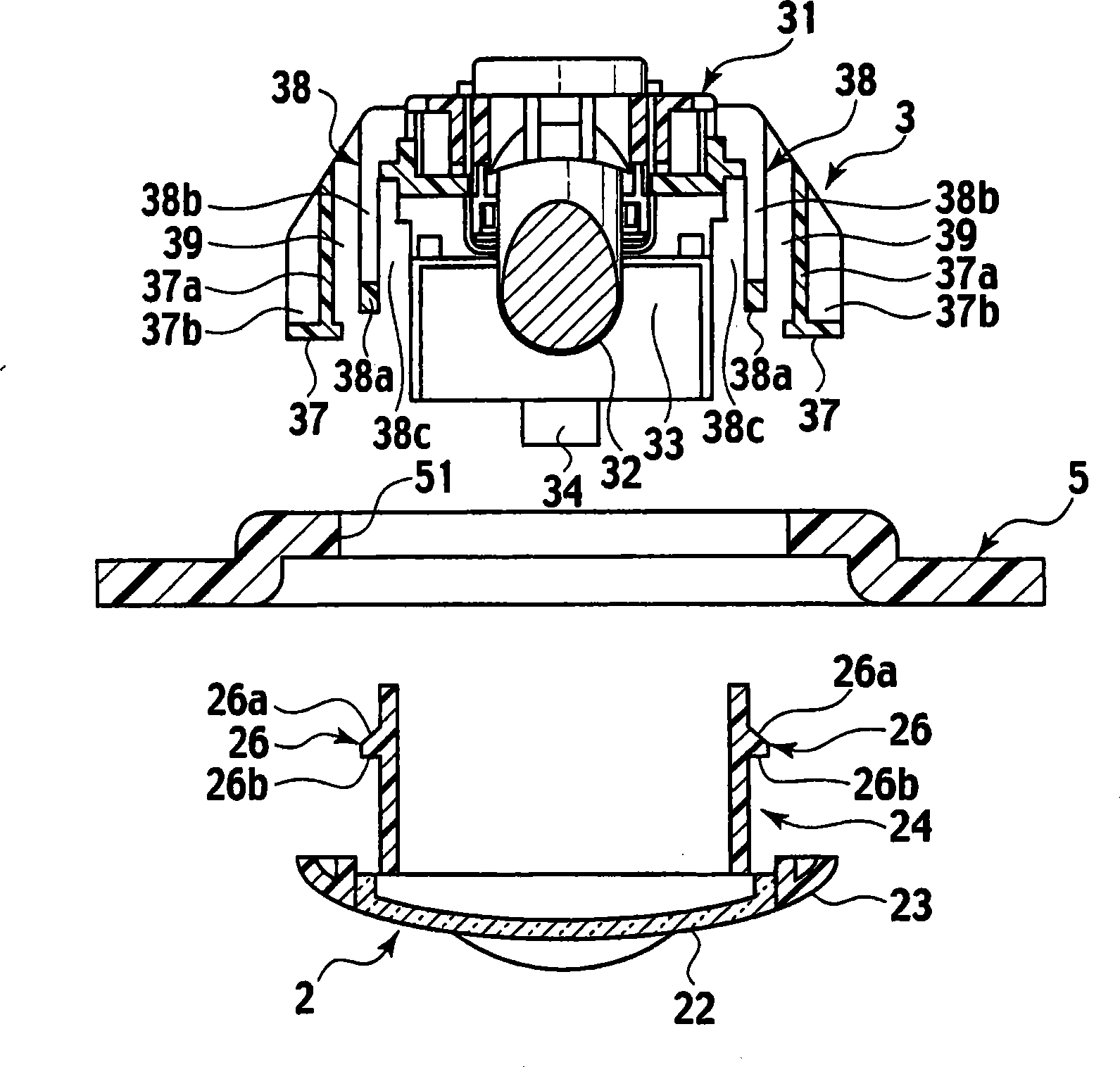
[0086] That is, in the first embodiment, it is set so that the displacement of the left and right pair of locked parts 38a in the release direction can be prevented by one positioning part 4, and in the third embodiment, it is set so that it can be prevented by two positioning parts 4B having the same structure. Displacement in the release direction of the pair of left and right locked portions 38 a is prevented.
[0087] Such as Figure 21A , 21B As shown, each positioning portion 4B includes an insertion plate portion 60, a stop portion 61 projecting laterally from the rear end of the insertion plate portion 60 in the insertion ...
PUM
 Abstract
Description
Claims
Application Information