

Fuel injector
A technology of fuel injectors and injectors, applied in fuel injection devices, fuel injection devices with sensors, instruments, etc., can solve problems such as pressure sensor damage
- Summary
- Abstract
- Description
- Claims
- Application Information
AI Technical Summary
Problems solved by technology
Method used
Image

Examples
Embodiment Construction
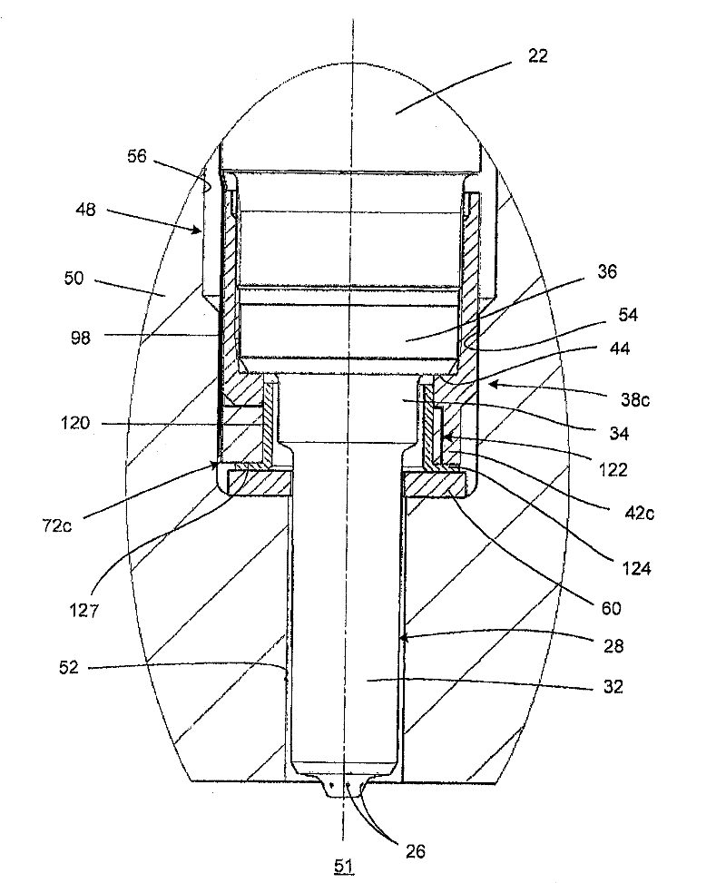
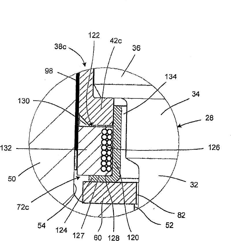
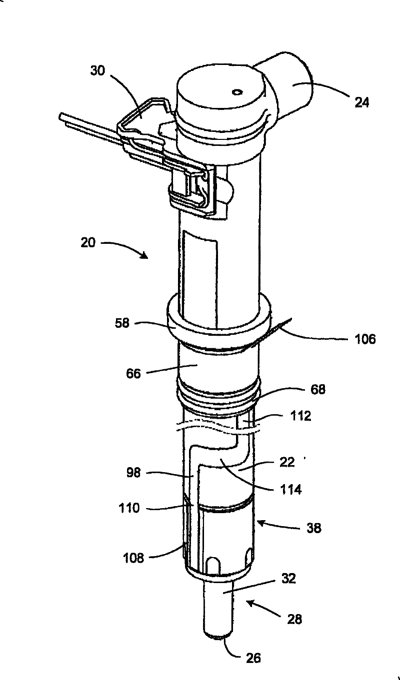
[0042] In the remainder of this document, the terms "upper" and "lower" refer to the orientation of the fuel injectors in the respective figures. However, it should be appreciated that, in use, the fuel injectors may be arranged in any suitable spatial orientation. The terms "outer" and "inner" are used with reference to an origin located on the longitudinal axis of the fuel injector.
[0043] see Figures 1 to 3 , in a first embodiment of the present invention, a fuel injector 20 is provided that includes a generally tubular injector body 22 . The injector body 22 houses components mounted to allow control of fuel passage from a fuel inlet 24 to an outlet 26 provided in a nozzle housing 28 adjacent the lowermost end of the injector body 22 . Such a component arrangement and its operation are described, for example, in the applicant's European patent EP 0995901 B. In this arrangement, in use, the piezoelectric actuator controls the movement of the valve needle housed in the...
PUM
 Abstract
Description
Claims
Application Information