Needle thread feeding device for multi-needle embroidery sewing machine

A feeding device and sewing machine technology, applied in the direction of sewing machine metering device, sewing machine components, embroidery machine mechanism, etc., can solve the problems of detrimental embroidery pattern style, complex structure of sewing machine head, and time-consuming threading, etc., to improve quality and style , Eliminate winding defects, reduce the number of rolls

Active Publication Date: 2009-12-09
BARUDAN KK
View PDF6 Cites 8 Cited by
  • Summary
  • Abstract
  • Description
  • Claims
  • Application Information

AI Technical Summary

Problems solved by technology

[0004] However, according to the conventional needle thread feeding device, since the same number of feeding rollers as needles are required, not only the rollers but also the number of gears of the switching mechanism are increased, and there is a problem that the structure of the sewing machine head is complicated.
In addition, in order to wind the upper thread around each feed roller, not only it takes man-hours to thread the thread, but also in the case of using a weak upper thread such as a loosely twisted thread, there is a winding defect and the style of the embroidery pattern may be damaged. question

Method used


Image

  • Needle thread feeding device for multi-needle embroidery sewing machine
  • Needle thread feeding device for multi-needle embroidery sewing machine
  • Needle thread feeding device for multi-needle embroidery sewing machine

Examples


Embodiment 1

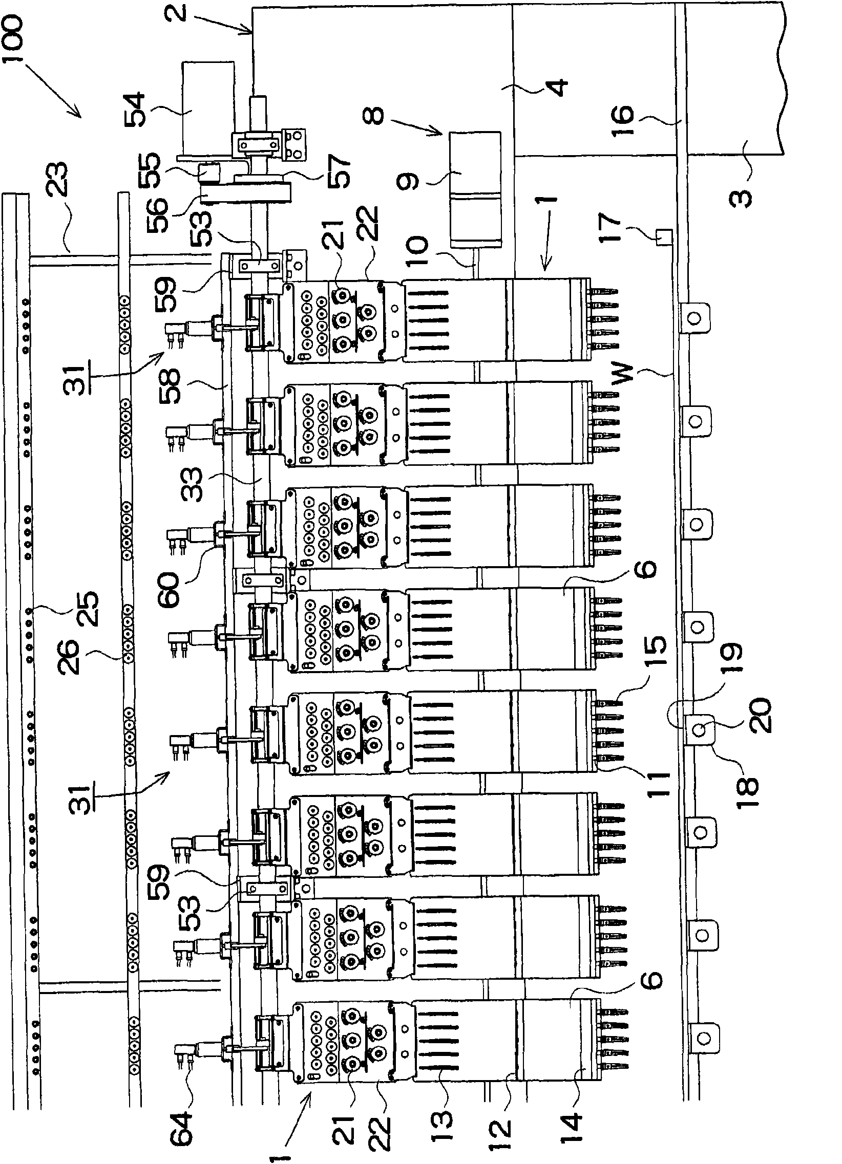
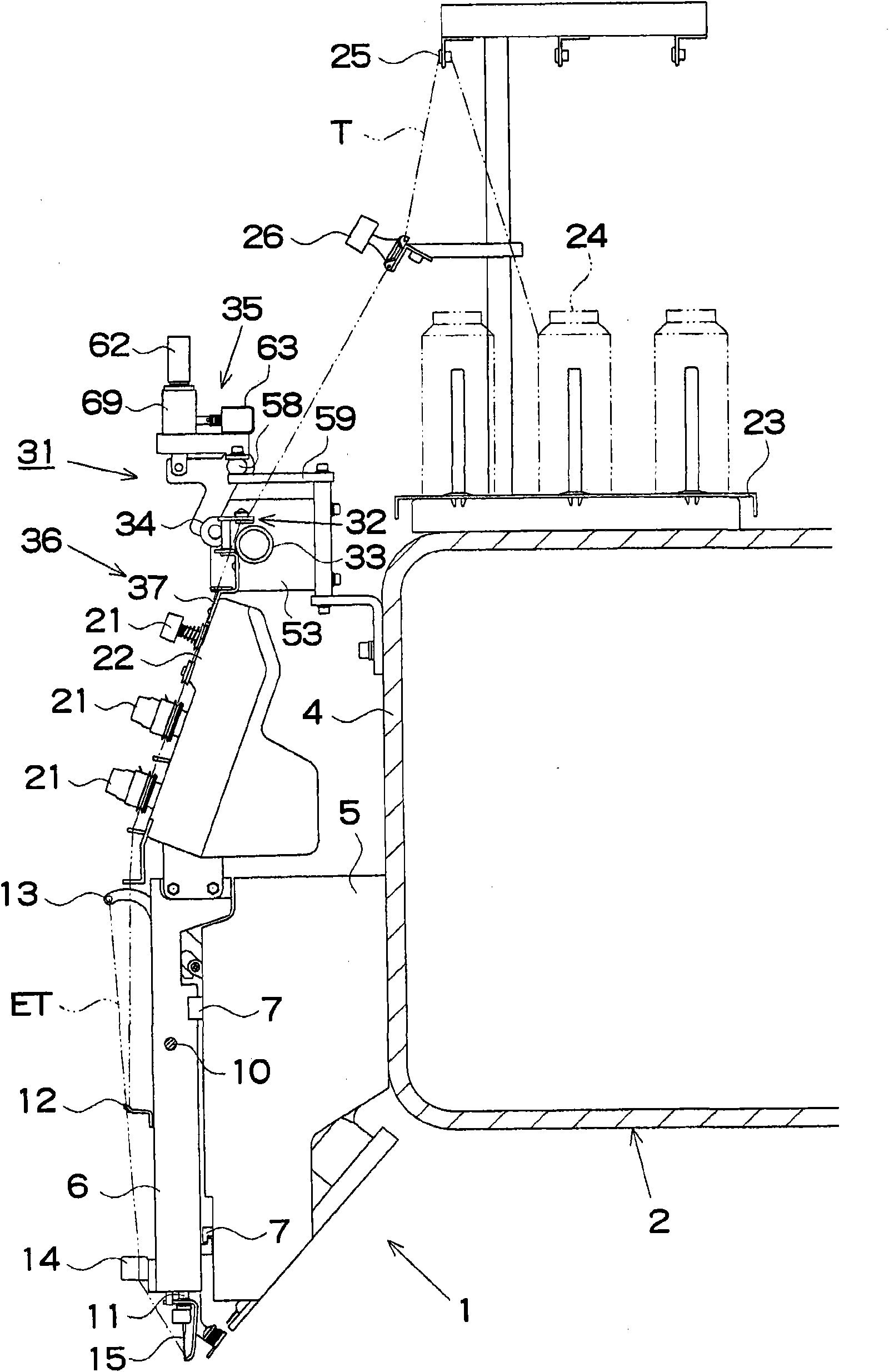
[0014] Below, according to Figure 1~Figure 8 , Describe Embodiment 1 of the present invention. Such as figure 1 , figure 2 As shown, the multi-head embroidery sewing machine 100 of this embodiment is constructed by arranging a plurality of (for example, 56) multi-needle embroidery sewing machines 1 in the left-right direction of the machine frame 2. The sewing machine frame 2 includes a pillar portion 3 and a beam portion 4, and an arm 5 of the multi-needle embroidery sewing machine 1 is provided protruding in front of the beam portion 4. On the front of the sewing machine arm 5, the sewing machine head 6 is slidably supported by a rail 7 in the left-right direction, and all the heads 6 of the embroidery sewing machine 1 are driven by the motor 9 of the color changing mechanism 8 via the connecting rod 10 at one time.

[0015]A plurality of (for example, five) needle bars 11, a thread guide 12, a thread take-up 13 and a thread clamp 14 are arranged on the sewing machine head 6,...

Embodiment 2

[0034] Then, according to Figure 9~Figure 11 , Describe the second embodiment of the present invention. The upper thread feeding device 81 of embodiment 2, such as Picture 9 , Picture 10 As shown, the upper thread guide mechanism 82 and the driving roller 83 are arranged on the beam portion 4 of the sewing machine frame 2, and the pressing roller 84 is movably provided relative to the beam portion 4, and the wiring mechanism 86 presses against the upper thread guide mechanism 82 The roller 84 and the switching mechanism 35 are configured to move in the axial direction of the driving roller 83. Next, a configuration different from that of the first embodiment will be described. In the figure, the same reference numerals as in the first embodiment indicate the components already described.

[0035] Such as Picture 10 , Picture 11 As shown, the upper thread guide mechanism 82 is provided with two thread guides 87 and 88 opposed vertically at approximately the same interval as th...

Embodiment 3

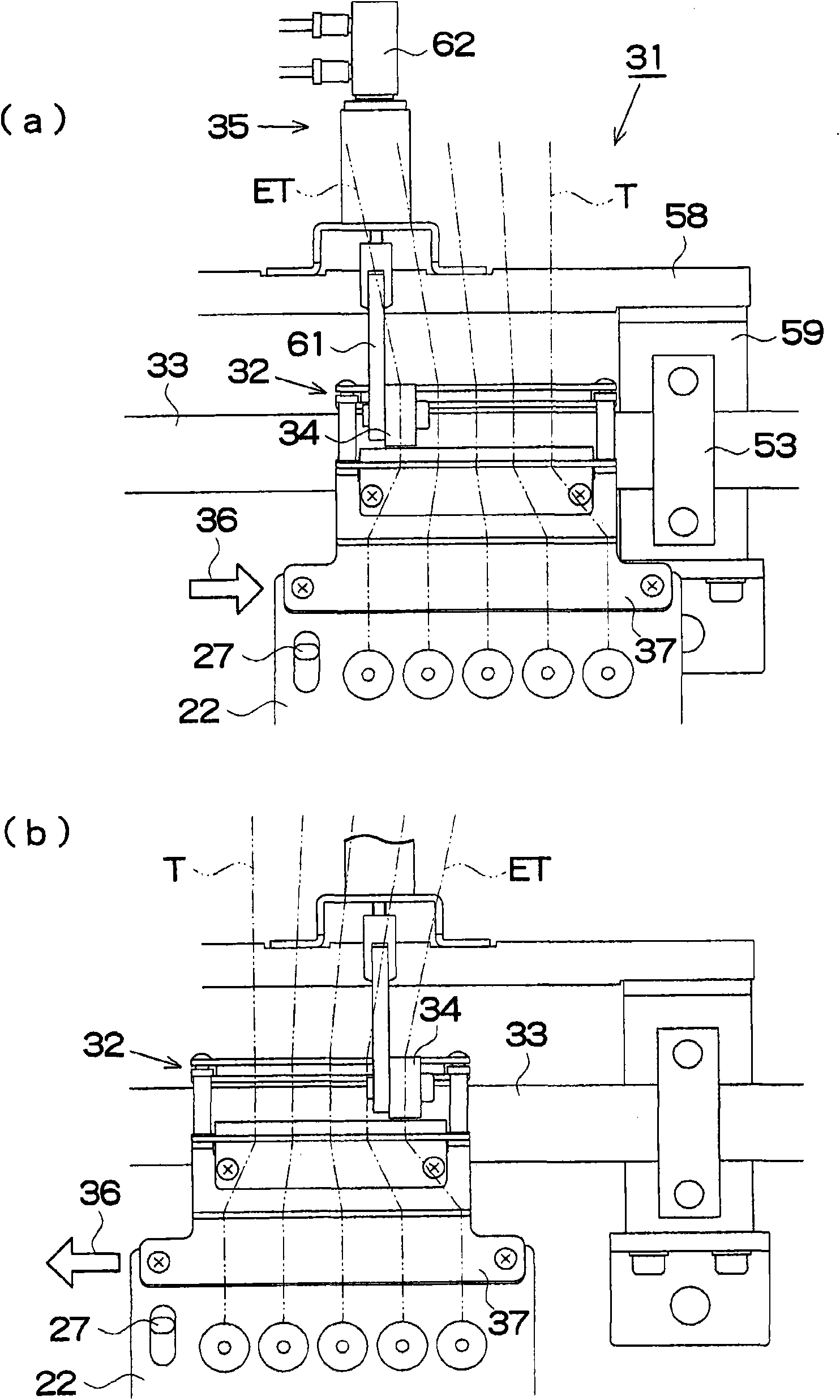
[0038] Then, according to Figure 12 ~ Figure 14 , Describe the third embodiment of the present invention. The third embodiment and the first embodiment are different from each other in that the tensioning table 22 is not provided, and in that a different upper thread feeding device 109 is provided instead of the upper thread feeding device 31 of the first embodiment. Next, the difference between this other upper thread feeding device 109 and the upper thread feeding device 31 of the first embodiment will be described. In the figure, the same reference numerals as in the first embodiment indicate the components already described.

[0039] The upper thread feeding device 109 does not include the base 37 mounted on the tension table 22, and includes the clamp portion 110, the opening and closing mechanism 140, and the controller (not shown) shown below. This is the same as the first embodiment. The upper thread feeding device 31 is different. In addition, the switching mechanism 35, ...


PUM


Abstract

The present invention provides a needle thread feeding device for a multi-needle embroidery sewing machine that moves a sewing machine head to selectively locate one of a plurality of needles in a sewing position, and feeds out, out of a plurality of needle threads, a selected needle thread passing through the needle in the sewing position from a needle thread supply source to the needle, the needle thread feeding device includes a drive roller having a length that extends across the plurality of needle threads, a needle thread guide mechanism that arranges the needle threads side by side in an axial direction of the drive roller and guides the needle threads, a pressure roller that presses the selected needle thread onto the drive roller, and a thread distributing mechanism that relatively moves the needle thread guide mechanism and the pressure roller in the axial direction of the drive roller in synchronization with movement of the sewing machine head. The thread distributing mechanism interposes the selected needle thread between the drive roller and the pressure roller.

Description

Technical field [0001] The present invention relates to an upper thread feeding device for a multi-needle embroidery sewing machine that sends a selected upper thread of a needle passing through a sewing position among a plurality of upper threads from an upper thread supply source to the needle. Background technique [0002] Generally, a multi-needle embroidery sewing machine passes the upper threads of different colors through the multiple needles set on the sewing machine head, and the color changing mechanism moves the sewing machine head to place a needle at the sewing position. The selected upper thread passed through by the needles forms a multi-color embroidery pattern on the processed cloth on the embroidery frame. In this kind of embroidery sewing machine, in the past, based on the movement amount of the embroidery frame, the amount of the selected upper thread was determined in advance by considering the material of the upper thread and the cloth, and a predetermined a...

Claims


Application Information

Patent Timeline
Patent Type & Authority Applications(China)
IPC IPC(8): D05B47/00D05B51/00
CPCD05C11/08D05B45/00D05B47/04D05C11/10
Inventor 浅井政志柳谷荣吉水野信一
Owner BARUDAN KK
Why Eureka
Try Eureka