

Pressure-type temperature controller
A thermostat and pressure-type technology, applied in the field of mechanical thermostats, can solve the problems of compressor damage, failure to popularize and use, failure to start normally, etc., to achieve the effect of simplifying the electrical structure and saving costs
- Summary
- Abstract
- Description
- Claims
- Application Information
AI Technical Summary
Problems solved by technology
Method used
Image

Examples
Embodiment Construction
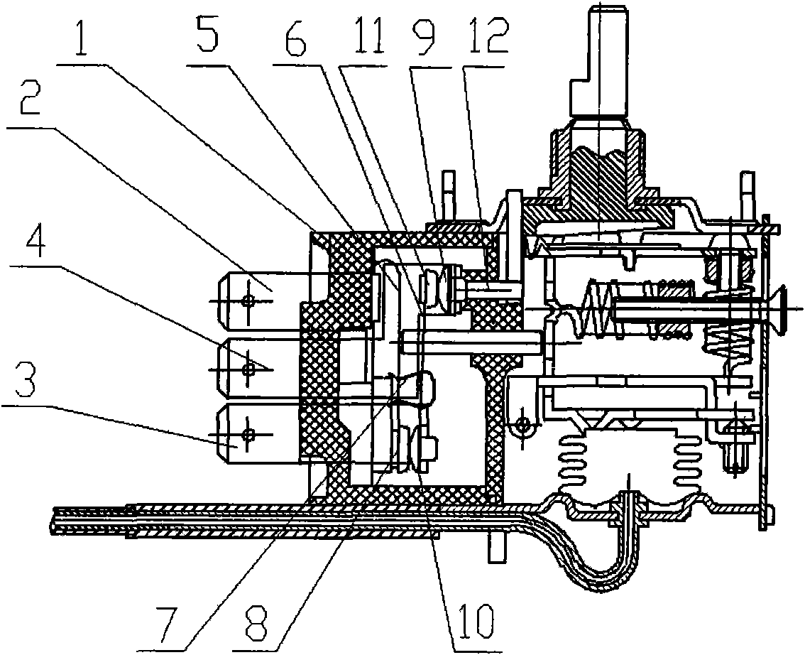
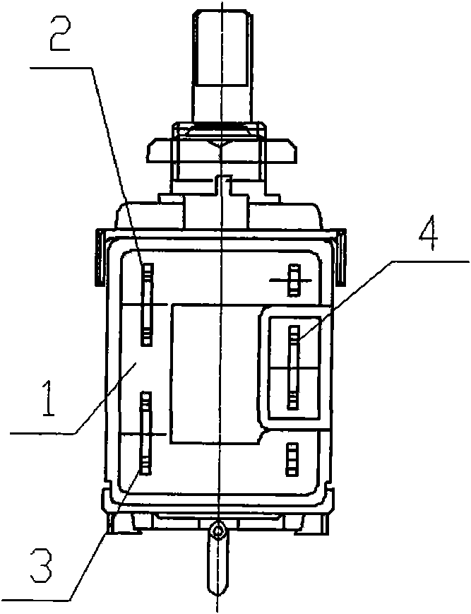
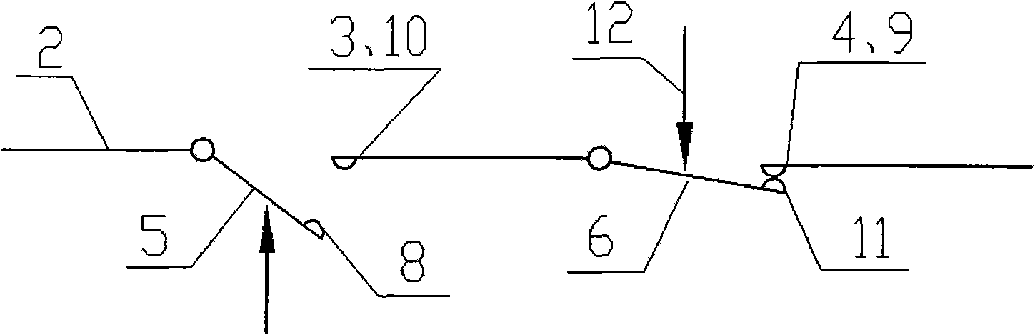
[0023] see Figure 5 to Figure 8 As shown, a single-pole double-throw pressure type thermostat with auxiliary switch is composed of a bellows 17 in the main body, a pressure bearing plate 18, a temperature adjustment spring, an adjustment shaft assembly and a switch box assembly, wherein the switch box assembly consists of a switch box 16. C terminal 2, L terminal 3, H terminal 4, moving contact 5, auxiliary contact 15, bow spring 7, C moving contact 8, H static contact 9, L static contact 10, auxiliary contact 11 , M terminal 13, M static contact 14, and auxiliary push rod 12. C terminal 2, C moving contact 8, moving contact piece 5, bow spring 7, L terminal 3, L static contact 10, M terminal 13, and M static contact 14 constitute a single-pole, double-pole switch that is controlled by temperature and produces a sudden jump action. Throw the switch. Auxiliary push rod 12, H terminal 4, H static contact 9, auxiliary contact 11, auxiliary contact piece 15, and C terminal 2 fo...
PUM
 Abstract
Description
Claims
Application Information