

Crankshaft driving mechanism of press machine
A crankshaft drive and press technology, which is applied to the driving device of forging presses, presses, stamping machines, etc., can solve the problems of gear wear, unbalanced load, large torque, etc., and achieve less impact and reduce gear damage Accidents, reducing the effect of uneven local stress
Inactive Publication Date: 2010-09-29
段巧荣
View PDF0 Cites 0 Cited by
- Summary
- Abstract
- Description
- Claims
- Application Information
AI Technical Summary
Problems solved by technology
[0003] The object of the present invention is to provide a crankshaft drive mechanism of a press, which overcomes the existing problems of the crankshaft drive mechanism of a press, which are prone to force stress due to large torque, errors in crankshaft manufacturing and installation. Caused by eccentric load: it is easy to cause abnormal wear and damage to the gears directly installed on the crankshaft and the gears meshing with it
Method used
View moreImage
Smart ImageViewing Examples

Examples
Embodiment Construction
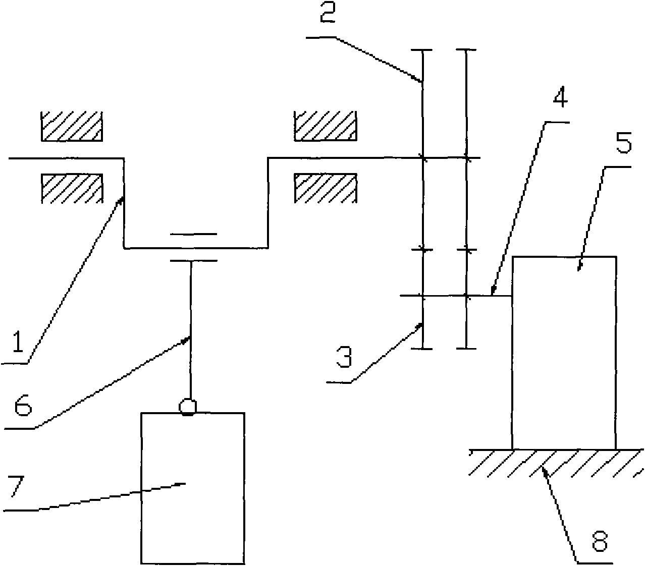
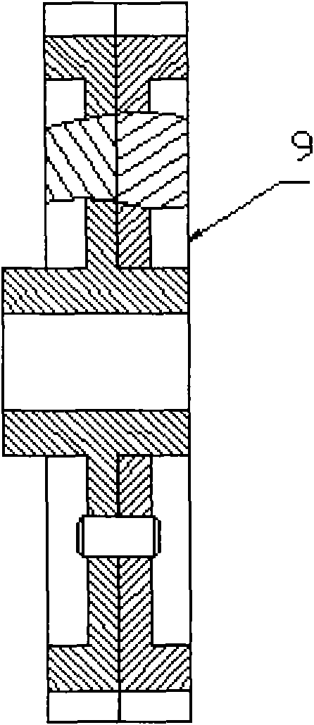
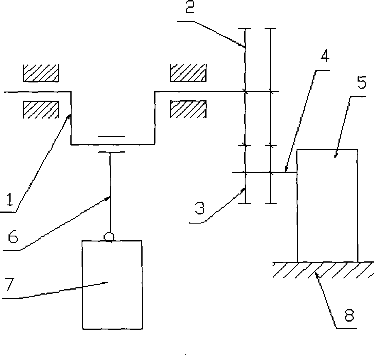
[0009] Correctly install the double herringbone gear (2) at the crankshaft end on the top of the crankshaft (1), correctly install the double herringbone gear (3) at the output shaft end of the gearbox on the top of the output shaft (4) of the gearbox, and place the gear The box (5) is installed on the bed (8) of the press, and the double herringbone gear (2) at the end of the crankshaft is properly meshed with the double herringbone gear (4) at the output shaft end of the gearbox. Correctly install the connecting rod (6) with the crankshaft (1), correctly connect the connecting rod (6) with the slider (7), and install other transmission parts.
Login to View More PUM
 Abstract
The invention relates to a crankshaft driving mechanism of a press machine. In the crankshaft driving mechanism, a duplex herringbone gear at a crankshaft end is correctly arranged on a crankshaft; a duplex herringbone gear at an output shaft end of a gear case is correctly arranged on the output shaft of the gear case; the gear case is arranged on a lathe bed of the press machine; and the duplex herringbone gear at the crankshaft end is ensured to be correctly engaged with the duplex herringbone gear at the output shaft end of the gear case. A connecting rod and the crankshaft are correctly arranged on the crankshaft driving mechanism; the connecting rod is correctly connected with a sliding block; and other delivery parts are correctly arranged on the crankshaft driving mechanism.
Description
technical field [0001] The invention relates to a crankshaft driving mechanism, in particular to a crankshaft driving mechanism of a press. It belongs to the technical field of forging machinery. Background technique [0002] The crankshaft is the main part of the pressure output of the mechanical press. In the actual work of the press, it is often found that the drive gear installed on the crankshaft and the gear meshing with the drive gear are easily damaged and worn. The main reason for this is that the crankshaft is in the transmission The lowest speed stage of the system bears the largest torque in the entire transmission system. At the same time, the crankshaft is also a part of the pressure output, which bears a large impact during work. Therefore, it is easy to cause adverse effects on the gears directly installed on the crankshaft and the gears meshing with it. Contents of the invention [0003] The object of the present invention is to provide a crankshaft driv...
Claims
Login to View More Application Information
Patent Timeline
 Patent Type & Authority Applications(China)
IPC IPC(8): B30B1/26B21J9/18
CPCB30B1/266
Inventor 段巧荣
Owner 段巧荣