Vibration detection platform

A technology of vibration detection and workbench, which is applied in the field of detection and can solve problems such as inability to withstand vibration and reliability evaluation

Inactive Publication Date: 2011-08-03
CHANGCHUN INST OF OPTICS FINE MECHANICS & PHYSICS CHINESE ACAD OF SCI
View PDF7 Cites 13 Cited by
  • Summary
  • Abstract
  • Description
  • Claims
  • Application Information

AI Technical Summary

Problems solved by technology

Since the greater the load of the spring in the compressed state, the smaller the amplitude of the vibration, so this kind o

Method used


Image

  • Vibration detection platform
  • Vibration detection platform
  • Vibration detection platform

Examples


Embodiment 1

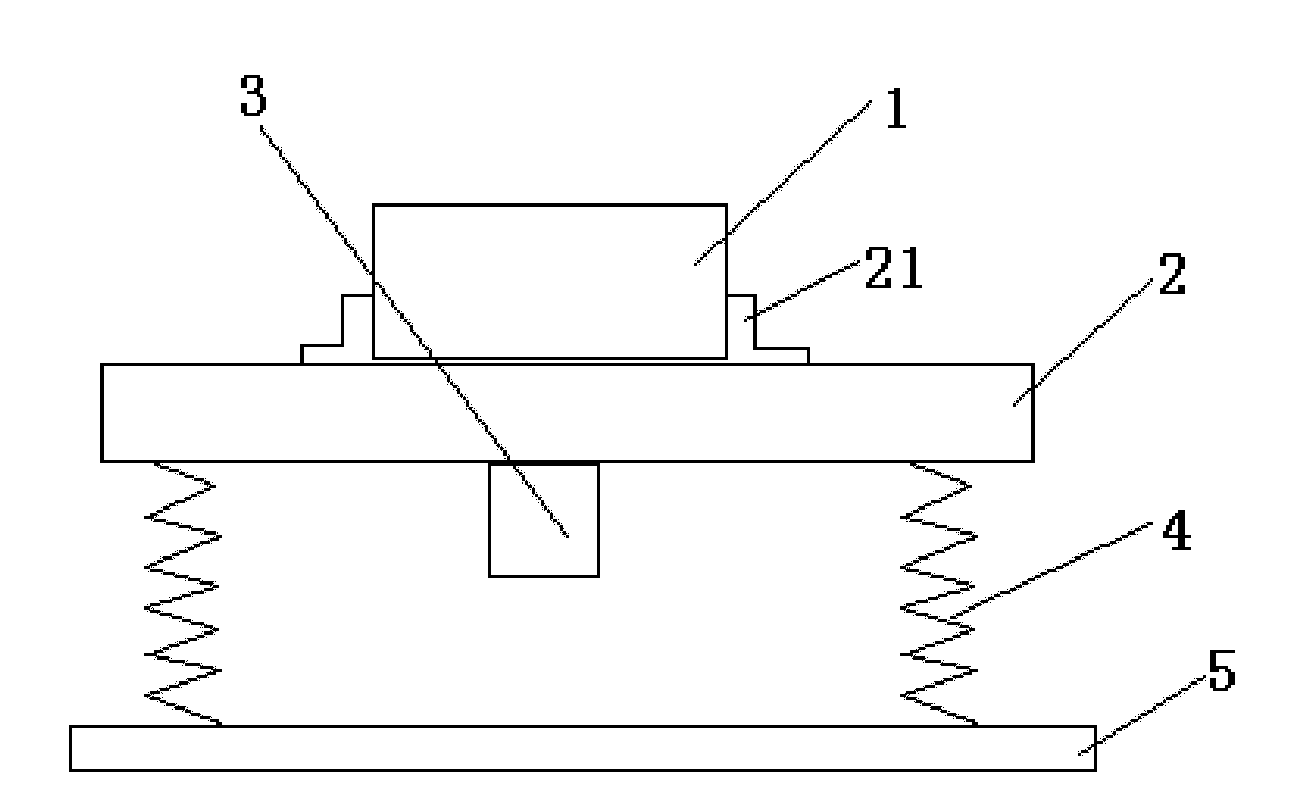
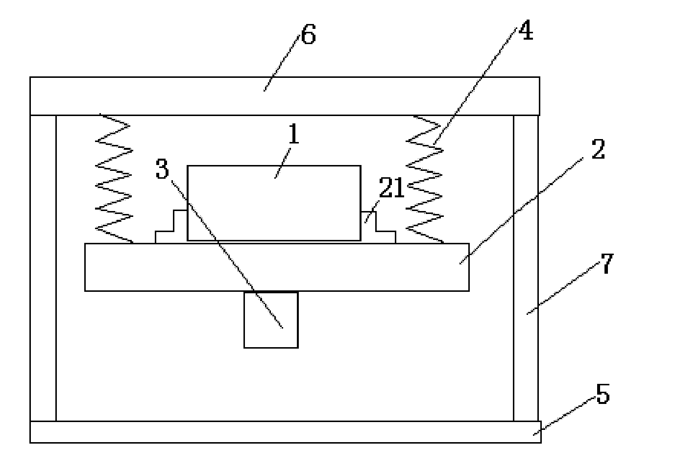
[0020] like figure 2 As shown, the vibration detection table of the present invention includes a base 5, a vibrator 3, a workbench 2 with a locking device 21 on the upper surface, 5 tension springs 4, and a support; the vibrator 3 is fixed on the working Below the platform 2, the product under test 1 is fixed on the workbench 2; the bracket is composed of a horizontal plate 6 and a column 7; the column 7 is vertically fixed on the base 5, and its upper end is fixedly connected with the horizontal plate 6; the tension spring 4 One end of it is connected with the horizontal plate 6, and the other end is connected with the workbench 2, so that the workbench 2 is suspended above the base 5.

Embodiment 2

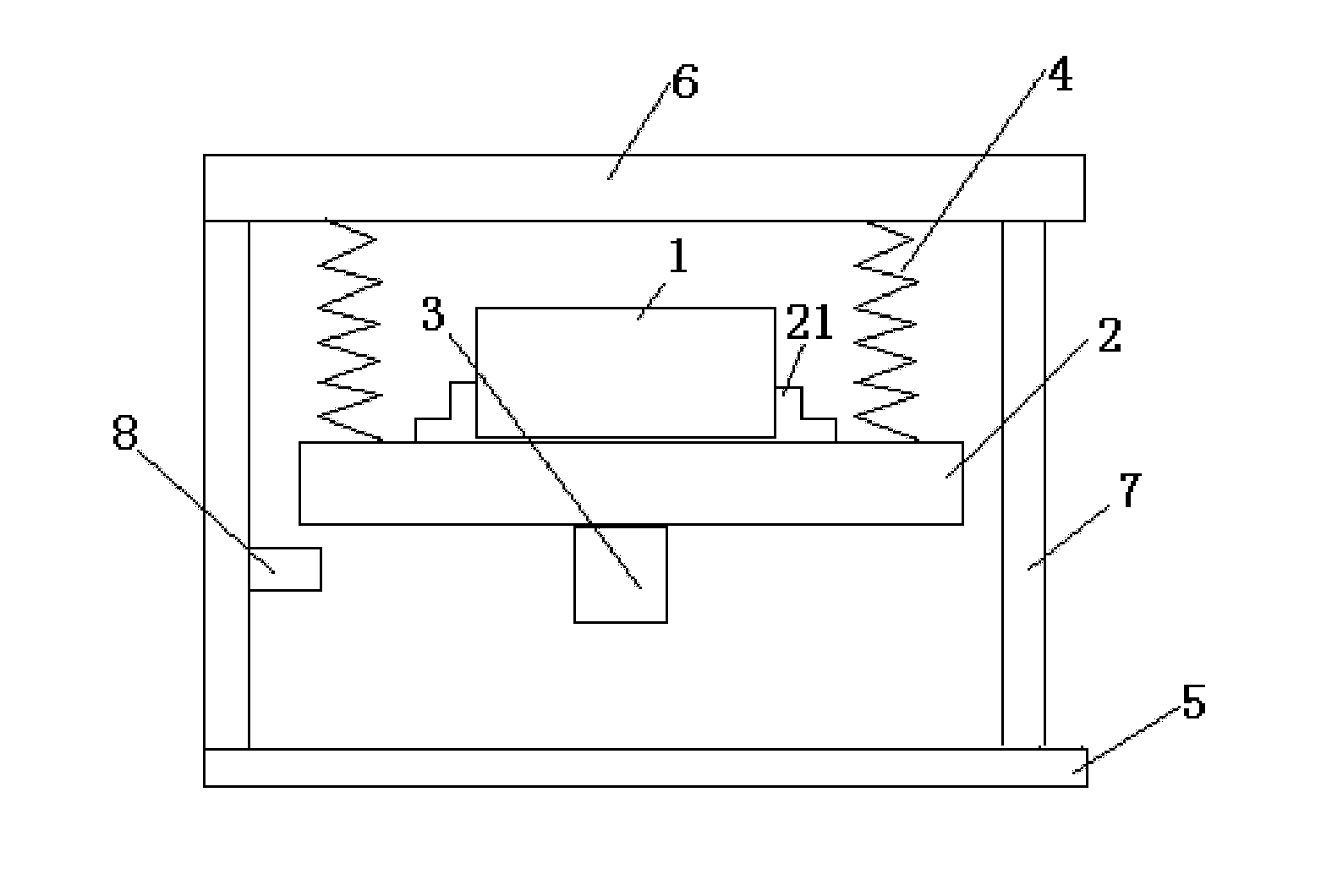
[0022] like image 3 As shown, the vibration detection table of the present invention includes a base 5, a vibrator 3, a workbench 2 with a locking device 21 on the upper surface, 4 tension springs 4, a support, and a limit device 8; The instrument 3 is fixed under the workbench 2, and the product under test 1 is fixed on the workbench 2; the bracket is composed of a horizontal plate 6 and a column 7; the column 7 is vertically fixed on the base 5, and its upper end is fixedly connected with the horizontal plate 6 One end of the tension spring 4 is connected with the horizontal plate 6, and the other end is connected with the workbench 2, so that the workbench 2 is suspended above the base 5; When the surface is in contact with the limiting device 8, the stress on the extension spring 4 does not exceed its elastic limit.

Embodiment 3

[0024] like Figure 4 As shown, the vibration detection table of the present invention includes a base 5, a vibrator 3, a workbench 2 with a locking device 21 on the upper surface, a tension spring 4, a support, and a limit device 8; the vibrator 3 is fixed under the workbench 2, and the product under test 1 is fixed on the workbench 2; the bracket is composed of a horizontal plate 6 and a column 7; the column 7 is vertically fixed on the base 5, and its upper end is fixedly connected with the horizontal plate 6; One end of the tension spring 4 is connected with the column 7, and the other end is connected with the workbench 2, so that the workbench 2 is suspended above the base 5; the limit device 8 is fixed on the column 7, and when the lower surface of the workbench 2 When the limit device 8 is in contact, the stress on the extension spring 4 does not exceed its elastic limit.


PUM


Abstract

The invention relates to a vibration detection platform. A vibration exciter of the detection platform is fixed below a worktable with a locking device on the upper surface; a bracket is fixed on a base; one end of an extension spring is connected with a bracket, and the other end of the extension spring is connected with the worktable; and the worktable is suspended over the base. The vibration exciter generates a vibrating force to allow the worktable to drive a detected product fixed on the worktable to vibrate, the completeness of the product is observed after a given time period of vibration, and thus, the vibration resistance and reliability of the product can be evaluated. In the invention, accurate vibration resistance and reliability evaluation can be delivered no matter the mass of the product is high or low or variable in a detection process, and the vibration detection platform is particularly suitable for detecting the vibration resistance and reliability of products in aerospace field.

Description

technical field [0001] The invention belongs to the technical field of detection, and relates to a vibration detection platform for detecting the anti-vibration performance of products. Background technique [0002] Vibration testing table is a kind of equipment that uses mechanical vibration to simulate the vibration environment encountered by products during manufacturing, assembly, transportation and use, so as to evaluate the vibration resistance, reliability and integrity of product structures. For example, relevant vibration tests are carried out on samples in laboratories and production lines of auto parts, electronic components, components, medicine, food, furniture, gifts, ceramics, packaging and other industries. With the improvement of reliability requirements for products, especially aerospace products, the vibration detection table as the key equipment of reliability test is becoming more and more important. [0003] The currently used vibration detection table...

Claims


Application Information

Patent Timeline
IPC IPC(8): G01M7/02
Inventor 张尧禹李贺军
Owner CHANGCHUN INST OF OPTICS FINE MECHANICS & PHYSICS CHINESE ACAD OF SCI
Why Eureka
Try Eureka