Lamp and lighting equipment

A technology for lighting devices and lamp sockets, which is applied to lighting devices, lighting and heating equipment, and components of lighting devices. Effect of decrease in light distribution uniformity

Inactive Publication Date: 2011-09-07
TOSHIBA LIGHTING & TECH CORP
View PDF1 Cites 2 Cited by
  • Summary
  • Abstract
  • Description
  • Claims
  • Application Information

AI Technical Summary

Problems solved by technology

[0005] However, this type of bulb-type lamp has the following problems: the connector frame blocks the light emitted from the LED, and the uniformity of light distribution may decrease.

Method used


Image

  • Lamp and lighting equipment
  • Lamp and lighting equipment
  • Lamp and lighting equipment

Examples


Embodiment Construction

[0078] Hereinafter, an embodiment of the present invention will be described with reference to the drawings.

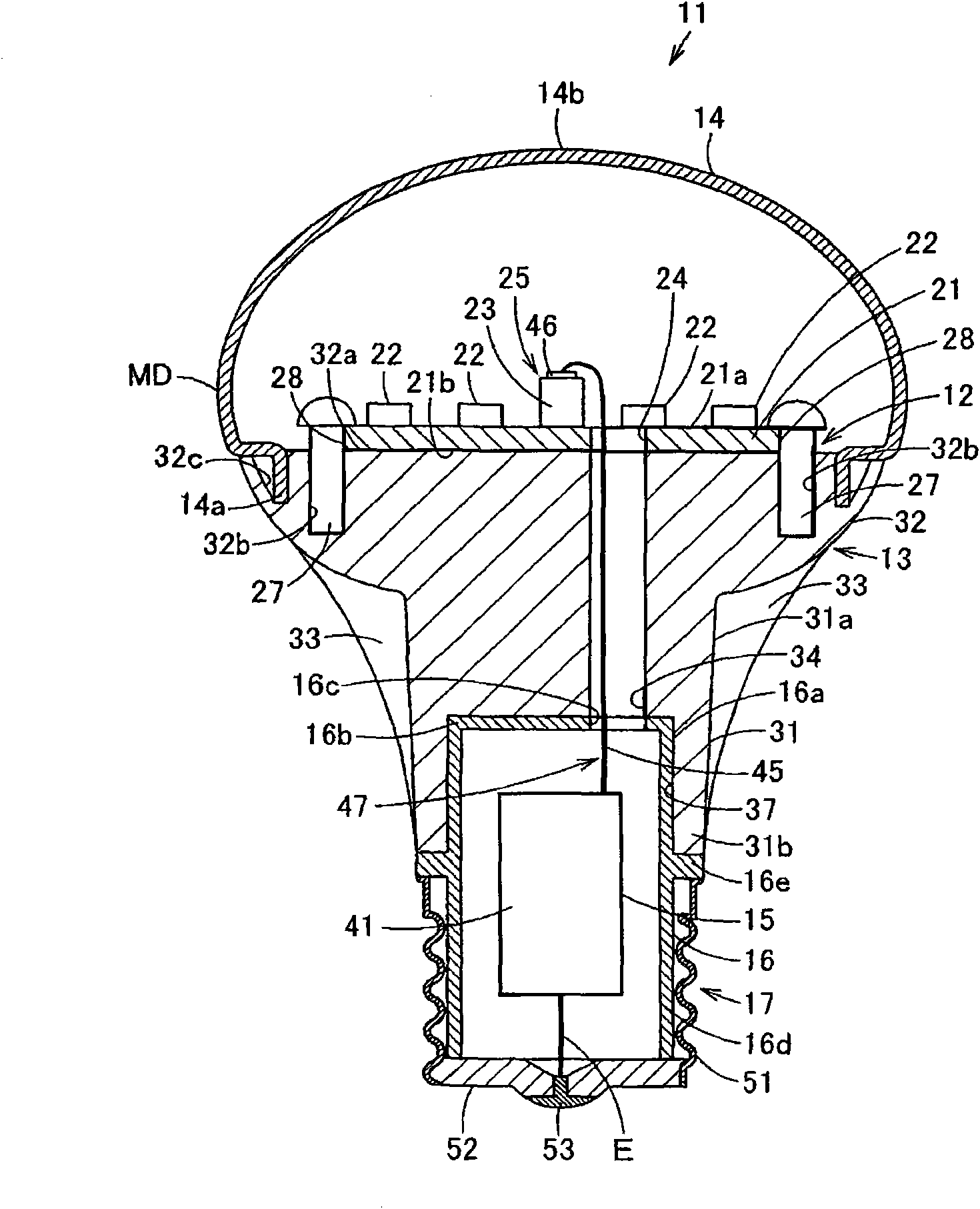
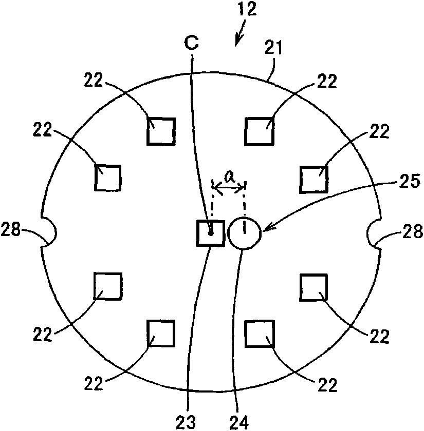
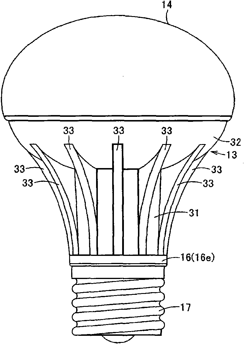
[0079] Figure 1 to Figure 4 The table shows the first embodiment, figure 1 is a longitudinal sectional view of the lamp device, figure 2 is a plan view of the element substrate of the lamp device, image 3 is the side view of the light fixture, Figure 4 It is an explanatory drawing schematically showing the state in which the lighting fixture to which the said lamp apparatus was attached was installed on the ceiling surface.

[0080] exist figure 1 and image 3 Among them, 11 represents a bulb-type lamp as a lamp device, that is, a bulb-type LED lamp. The structure of this bulb-type LED lamp 11 is as follows: an LED substrate 12 as an element substrate is mounted on one end side of a radiator 13, and a lampshade 14 covers the LED substrate 12. Installed on one end side of this radiator 13, on the other end side of this radiator 13, is installed an insulating ...


PUM


Abstract

The invention relates to a lamp and the lighting equipment. The lamp includes: an element substrate, a heat radiator, a lamp socket, a receiving box, a lighting device and a heat conducting member. The element substrate has a light emitting element. The element substrate is installed on one end of the heat radiator and the other end of the heat radiator has a receiving recess. The lamp socket is installed on the other end side of the heat radiator. The receiving box is disposed in the receiving recess of the heat radiator; a part of the receiving box includes an opening part which is communciated with the receiving recess. The lighting device is received in the receiving box and performs the lighting control to the light emitting element. The heat conducting member passes through the opening part of the receiving box and the lighting device is in thermal connection with the surface of the receiving recess of the heat radiator.

Description

[0001] This application is a divisional application of the original application number 200910160870.4, the application date is July 28, 2009, and the invention name is "lamp device and lighting appliance". technical field [0002] The present invention relates to a lamp device and a lighting fixture including an element substrate on which a plurality of light emitting elements are arranged. Background technique [0003] Previously, with regard to a lamp device using a light emitting diode (Light Emitting Diode, LED) as a light emitting element, that is, an LED lamp (lamp), for example, as disclosed in Japanese Patent Application Laid-Open No. 2006-313718, uniformly installed An LED substrate, which is an element substrate of the LED, is mounted on one end side of the heat sink, and a globe is mounted on one end side of the heat sink to cover the LED substrate. Further, a housing case containing a lighting device for controlling lighting of the LED substrate is inserted into ...

Claims


Application Information

Patent Timeline
Patent Type & Authority Applications(China)
IPC IPC(8): F21S2/00F21V29/00F21V23/00F21Y101/02
CPCF21V3/02F21V3/0427F21V23/002F21K9/00F21V29/246F21K9/1355F21V29/2231F21V23/006F21V3/0445F21Y2101/02F21V29/244F21V19/0055F21V29/773F21V29/87F21V29/89F21V29/508F21K9/23F21Y2115/10F21K9/238F21V3/0615F21V3/0625
Inventor 田中敏也久安武志大泽滋
Owner TOSHIBA LIGHTING & TECH CORP
Why Eureka
Try Eureka