Scaffold connector

A scaffolding and connecting piece technology, which is applied in the connection of scaffolding, house structure support, house structure support and other directions, can solve the problems of trouble and high assembly cost, and achieve the effect of good structural stability and convenient disassembly and assembly.

Inactive Publication Date: 2011-12-07
姚维华
View PDF0 Cites 6 Cited by
  • Summary
  • Abstract
  • Description
  • Claims
  • Application Information

AI Technical Summary

Problems solved by technology

[0002] Existing steel pipe anchor structures for scaffolding, such as figure 1 and figure 2 As shown, it is mainly composed of a U-shaped buckle 11, an arc-shaped cover 12 and two nuts 13, wherein the U-shaped buckle 11 is in a large U-shape for connecting two adjacent Two steel pipes 21, 22 are hooked into the inside of its curved arc, and then through the through hole 121 of the arc-shaped cover 12, the U-shaped buckle 11 is set between the two ends, and at the same time, the arc is tightened by two nuts 13. The cover body 12 firmly clamps the adjacent two scaffold steel pipes 21, 22 to achieve positioning; however, the relative predetermined angle of the two scaffold steel pipes 21, 22 is limited by the angle of the upper arc portion 122 of the arc-shaped cover body 12, In actual installation, it is necessary to prepare arc-shaped covers 12 with various angles to adapt to the installation angles of different scaffolding steel pipes 21, 22, which is not only troublesome, but also requires high assembly costs.

Method used


Image

  • Scaffold connector
  • Scaffold connector
  • Scaffold connector

Examples


Embodiment Construction

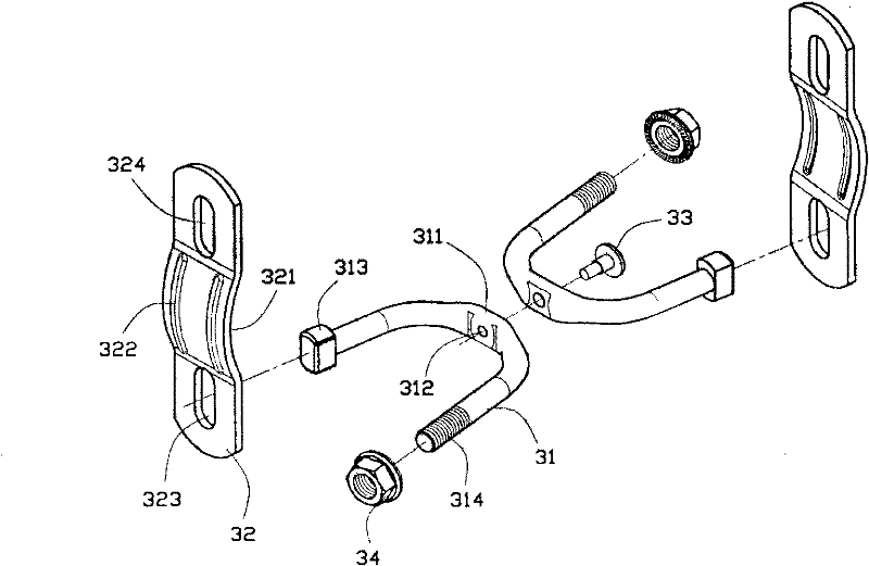
[0017] like image 3 and Figure 4 As shown, in the best embodiment of the present invention, the scaffold connector is composed of two corresponding U-shaped clasps 31 that are pivotally connected by riveting, and the two U-shaped clasps 31 are respectively matched. Two buckle parts 32 on one side of the opening are formed. Wherein, on the closed side of the U-shaped buckle 31, the middle part of the U-shaped buckle 31 is punched to form a flat wide surface 311, and a through hole 312 is opened on it, and the through hole 312 allows the rivet 33 to pass through. , and two corresponding U-shaped clasps 31 are riveted and assembled together, and the two U-shaped clasps 31 can rotate relatively freely around the central axis of the rivet 33, and the U-shaped clasps On one side of the 31 opening, one end of the U-shaped buckle 31 is set as a flat stopper 313, and the other end is set as a threaded section 314; the middle part of the buckle 32 is punched with an arc portion 321 ...


PUM


Abstract

The present invention provides a scaffold connector, which is composed of two corresponding U-shaped clasps that are pivotally connected to each other, and two buckles that are respectively disposed on one side of the opening of the two U-shaped clasps, wherein , a through hole is respectively provided in the middle part of the closed side of the two U-shaped buckles, a rivet passes through the through-hole and movably connects the two U-shaped buckles, and one end of the open side of the U-shaped buckle It is set as a flat stopper, and the other end is set as a threaded section; the middle part of the buckle is punched with a curved arc that can clamp the steel pipe of the scaffold, and the two ends of the buckle are respectively provided with elongated through holes, wherein , the elongated through hole at one end of the buckle fits the deformed stopper, and the elongated through hole at the other end of the buckle fits with the threaded section and a nut to connect the U-shaped buckle and the buckle. Compared with the prior art, the invention has the beneficial effects of helping the scaffolding to be quickly and conveniently disassembled and carried, and has good structural stability.

Description

technical field [0001] The invention relates to a scaffold connecting piece, in particular to a connecting piece used for connecting scaffold steel pipes. Background technique [0002] Existing steel pipe anchor structures for scaffolding, such as figure 1 and figure 2 As shown, it is mainly composed of a U-shaped buckle 11, an arc-shaped cover 12 and two nuts 13, wherein the U-shaped buckle 11 is in a large U-shape for connecting two adjacent Two steel pipes 21, 22 are hooked into the inside of its curved arc, and then through the through hole 121 of the arc-shaped cover 12, the U-shaped buckle 11 is set between the two ends, and at the same time, the arc is tightened by two nuts 13. The cover body 12 firmly clamps the adjacent two scaffold steel pipes 21, 22 to achieve positioning; however, the relative predetermined angle of the two scaffold steel pipes 21, 22 is limited by the angle of the upper arc portion 122 of the arc-shaped cover body 12, During actual installat...

Claims


Application Information

Patent Timeline
Patent Type & Authority Applications(China)
IPC IPC(8): E04G7/16
Inventor 姚维华
Owner 姚维华
Why Eureka
Try Eureka