Light conduction device and backlight device

A backlight device and light conduction technology, applied in the direction of light guide, lighting device, fixed lighting device, etc., can solve the problems of insufficient light uniformity, affecting the color of displayed images, etc., and achieve the effect of simplifying design and maintenance

Inactive Publication Date: 2012-01-11
BENQ CORP
View PDF4 Cites 8 Cited by
  • Summary
  • Abstract
  • Description
  • Claims
  • Application Information

AI Technical Summary

Problems solved by technology

[0004] Therefore, under the current structure of a line light source composed of several LEDs, whether it is due to abnormality or damage of a single LED, or the effect of ag

Method used


Image

  • Light conduction device and backlight device
  • Light conduction device and backlight device
  • Light conduction device and backlight device

Examples


Embodiment Construction

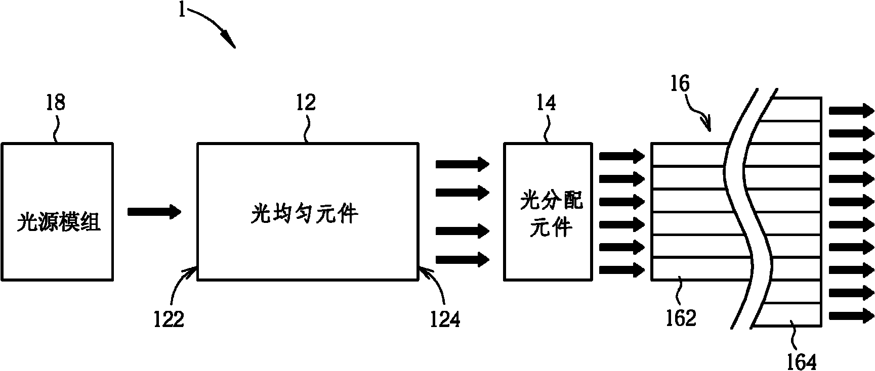
[0048] see figure 1 , which is a schematic structural diagram of the light transmission device 1 according to the present invention. The light transmission device 1 mainly includes a light uniform element 12 , a light distribution element 14 and a plurality of optical fibers 16 . The light uniform element 12 has a light incident side 122 and a light exit side 124 . Each optical fiber 16 has a light input end 162 and a light output end 164 , and the light input end 162 of each optical fiber 16 is adjacent to the light output side 124 . The light distribution element 14 is disposed between the optical fiber 16 and the light-emitting side 124 and includes a plurality of microlenses (not shown in the figure), respectively corresponding to the plurality of optical fibers 16 . Light (indicated by a thick black arrow) is emitted from the light source module 18, enters the light uniform element 12 through the light incident side 122 and is homogenized by the light uniform element 12...


PUM


Abstract

The invention relates to a light conduction device and a backlight device. The light conduction device comprises a light uniformity component, plural optical fibers and a light distribution component, wherein the light distribution component is arranged between the plural optical fibers and the light uniformity component and comprises plural micro-lenses; and the multiple micro-lenses respectively correspond to the multiple optical fibers so as to lead light rays emitted from the light uniformity component into the corresponding optical fibers. The backlight device comprises the light uniformity component, a light guide plate and the plural optical fibers, wherein the light incidence ends of the optical fibers are bundled and ranked into a circular light receiving region to receive the light rays emitted from the light uniformity component; and the light emergent ends of the plural optical fibers are in staggered arrangement according to the ranking position of the corresponding light incidence ends and are used for uniformly leading the light rays into the light guide plate. Thus, according to the light conduction device and the backlight device, the light rays can be evenly conducted, and the uniformity of backlight is improved.

Description

technical field [0001] The invention relates to a light-conducting device and a backlight device, in particular to a light-conducting device and a backlight device used in a display device. Background technique [0002] At present, the LCD screen usually uses a light guide plate to convert the line light source mainly composed of several Light-Emitting Diodes (LEDs) into a surface light source, so as to provide the backlight required by the LCD panel. In practical applications, these LEDs are usually set in series and the overall luminous power of the line light source is controlled by a single controller. However, the working status of these LEDs is different. When one of the LEDs is abnormal or damaged, unless the line light source is removed and replaced The LED needs to be replaced, and the uneven light distribution produced by the line light source cannot be improved. [0003] In addition, the line light source composed of several LEDs is still a combination of point l...

Claims


Application Information

Patent Timeline
IPC IPC(8): G02B27/09G02F1/13357F21S8/00F21V8/00
Inventor 陈世宾林信男黄气宝
Owner BENQ CORP
Why Eureka
Try Eureka