Solar heat utilization thermostatical control system based on flow control
What is AI technical title?
AI technical title is built by PatSnap AI team. It summarizes the technical point description of the patent document.
A constant temperature control and solar thermal technology, applied in solar heating systems, solar thermal energy, solar thermal power generation, etc., can solve the problems of high finished product prices of electric control valves, thermal protection of motors, easy damage of reduction gears, etc., and achieve significant energy saving benefits and Economic benefit, high constant temperature accuracy, low intelligent control effect
Inactive Publication Date: 2013-03-06
HUAZHONG NORMAL UNIV
View PDF7 Cites 0 Cited by
Summary
Abstract
Description
Claims
Application Information
AI Technical Summary
This helps you quickly interpret patents by identifying the three key elements:
Problems solved by technology
Method used
Benefits of technology
Problems solved by technology
However, the above two methods have the following problems: for the first method, its application is limited to electric energy as the energy supply form; for the second method, the price of the finished product of the electric control valve is relatively high, and it is easy to cause thermal protection of the motor, deceleration, etc. The gears are easy to be damaged, the module thyristor is easy to burn out and other faults, while the self-operated control valve has the disadvantages of low adjustment accuracy, not suitable for occasions with drastic temperature changes, and the fluid viscosity cannot be too high.
However, the above methods are not only very difficult to realize, but also cause huge waste of solar energy
Existing constant temperature control technology cannot achieve accurate constant temperature control effect by using solar energy for heating under the premise of ensuring greater economic benefits
Method used
Image
Click on the blue label to locate the original text in one second.
Reading with bidirectional positioning of images and text.
Examples
Embodiment Construction
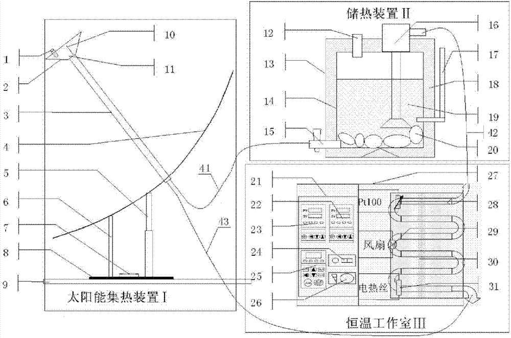
[0066] according to figure 1 It can be seen that the present invention includes solar heat collecting device I, heat storage device II, constant temperature studio III, three separate devices, plus a constant temperature control device IV integrated on the constant temperature studio III, consisting of four functional parts.
[0067] figure 1 Shown is a schematic diagram of the structure of the solar electric energy constant temperature control device. Including solar heat collection device I, heat storage device II, constant temperature studio III. Solar heat collection device I includes: mechanical valve 1, conical boiler 2, support pipe 3, plane group concentrating paraboloid 4, hydraulic cylinder 5, fixed pole 6, rotating bearing 7, rotating round table 8, flat support 9, heat transfer oil Output copper pipe 10, heat conduction oil input copper pipe 11. The mechanical valve 1 is installed on the upper surface of the cone boiler 2 to ensure the internal pressure of the b...
PUM
Abstract
The invention discloses a solar heat utilization thermostatical control system based on flow control. A solar heat collection device comprises a mechanical valve, a bevel-type boiler, a support tube, a planar group light condensation paraboloid, a hydraulic cylinder, a fixing strut, a swivel bearing, a swivel truncated cone, a flat plate bracket, a heat-conducting oil output copper tube and a heat-conducting oil input copper tube. A heat storage device comprises an oil filling orifice, an outer case body, a heat storage case, an outlet valve, a circulating pump, a liquid level display tube, athermal insulation layer, a heat-conducting medium and a heat storage medium. A thermostatic operating room comprises a thermostatic control device, a temperature controller function panel based on flow control, a temperature controller function panel based on electrothermal control, a power switch, a frequency modulator function panel, a blast fan speed-regulation knob, a case body of the original thermostatic operating room, a temperature sensor, a blast fan, a heat exchanger and a heating wire. By using the device, solar energy can be utilized for heat supply to realize the solar heat utilization thermostatical control based on fluid flow control.
Description
technical field [0001] The invention relates to a constant temperature control system based on flow control, and more particularly relates to a constant temperature control device for solar heat utilization based on fluid flow control. It is suitable for research and application fields such as laboratories, electronics, medicine, chemicals, food processing, agricultural scientific research, and environmental protection. Background technique [0002] In the fields of medical and scientific research, especially in the research of materials, a lot of research work needs to heat and dry materials and objects under constant temperature conditions, which puts forward higher requirements for constant temperature control technology. [0003] The existing constant temperature control technology at home and abroad mainly has two implementation methods: 1. In terms of electric heating energy supply, it mainly relies on the temperature controller system PID to control the heating resist...
Claims
Application Information
Patent Timeline
Application Date:The date an application was filed.
Publication Date:The date a patent or application was officially published.
First Publication Date:The earliest publication date of a patent with the same application number.
Issue Date:Publication date of the patent grant document.
PCT Entry Date:The Entry date of PCT National Phase.
Estimated Expiry Date:The statutory expiry date of a patent right according to the Patent Law, and it is the longest term of protection that the patent right can achieve without the termination of the patent right due to other reasons(Term extension factor has been taken into account ).
Invalid Date:Actual expiry date is based on effective date or publication date of legal transaction data of invalid patent.

