Road surface milling machine

A milling machine and milling technology, applied in the field of road construction machinery, can solve the problems of only lifting, high labor intensity, and inability to mill and plan, and achieve the effects of convenient operation, reduced labor intensity, and wide application range

Inactive Publication Date: 2013-10-23
于健 +1
View PDF8 Cites 0 Cited by
  • Summary
  • Abstract
  • Description
  • Claims
  • Application Information

AI Technical Summary

Problems solved by technology

[0002] At present, the milling machines for crushing old roads are all large self-propelled. The milling head is located in the middle of the wheel and can only be lifted up and down, and cannot move left and right. Therefore, it is only suitable for the overall renovation of the road surface and not for the local bad parts. , especially when it is impossible to mill to the roadside, the remaining part of the roadside during pavement repair has to be carried out manually, which is labor-intensive, labor-intensive, time-consuming, low in efficiency and high in cost

Method used


Image

  • Road surface milling machine
  • Road surface milling machine
  • Road surface milling machine

Examples


Embodiment Construction

[0019] In order to clearly illustrate the technical features of this solution, the present invention will be described in detail below through specific implementation modes and in conjunction with the accompanying drawings.

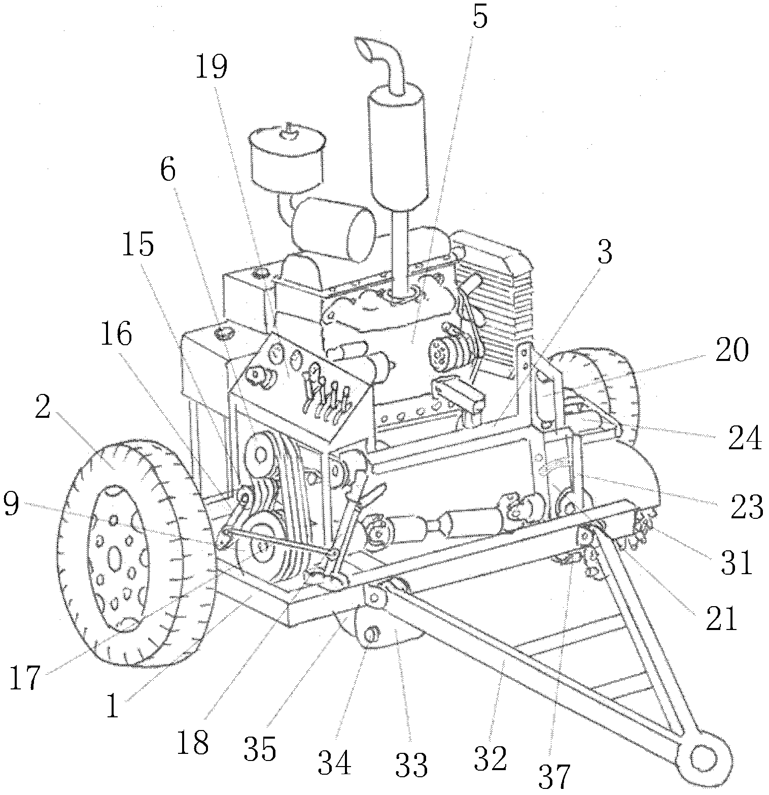
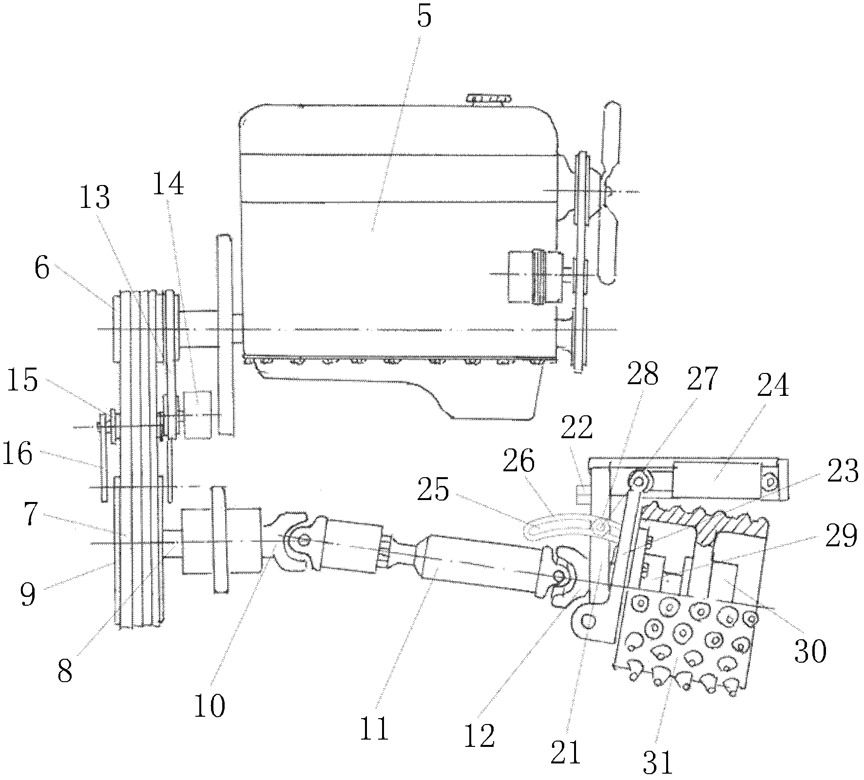
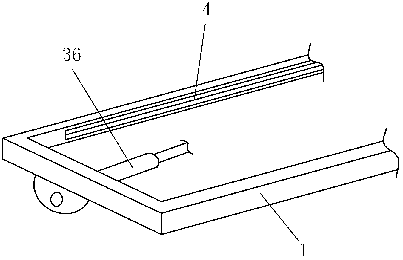
[0020] like Figure 1~3 Shown, the present invention comprises vehicle frame 1, is provided with wheel 2 at vehicle frame 1 left and right sides, is provided with traction device at vehicle frame 1 front, is provided with frame 3 above vehicle frame 1, and frame 3 bottom front and rear sides The side is inserted into the horizontal chute 4 on the vehicle frame 1, and a frame horizontal driving device is provided between the frame 3 and the vehicle frame 1; an internal combustion engine 5 is provided on the frame 1, and the output shaft of the internal combustion engine 5 is fixedly connected with Upper pulley 6, upper pulley 6 links to each other through the first belt 7 with the lower pulley 9 at one end of the intermediate shaft 8, which is fixed on the...


PUM


Abstract

A road surface milling machine comprises a vehicle frame and vehicle wheels, wherein a traction device is arranged at the front part of the vehicle frame; a machine frame is arranged above the vehicle frame, and the front and the rear sides at the bottom of the machine frame are inserted into horizontal sliding slots on the vehicle frame; a machine frame horizontal driving device is arranged between the machine frame and the vehicle frame; an internal combustion engine is arranged on the machine frame, and is connected with a milling device on one side of the vehicle frame via a first belt, a lower belt pulley, a first universal joint, a telescopic transmission shaft and a second universal joint; the milling device on one side of the vehicle frame is fixed on an inclination adjusting device; the inclination adjusting device is connected with a lifting device fixedly connected to the machine frame; the internal combustion engine is connected with a hydraulic pump fixed at the lower part on the rear side of the machine frame through a second belt; a tension belt pulley is arranged between the forward-inclined first belt and the backward-inclined second belt; a tension wheel shaft arm of the tension belt pulley is flexibly connected with the bottom of the machine frame; one end of a pull rod is flexibly connected with the middle part of the tension wheel shaft arm, and the other end of the pull rod is flexibly connected with an operating rod brake handle; and a control device is arranged on one side of the vehicle frame. The road surface milling machine is convenient to operate and low in cost, and has a high efficiency.

Description

Technical field: [0001] The invention relates to a road construction machine, in particular to a small road milling machine used for crushing and filling bad parts of old roads. Background technique: [0002] At present, the milling machines for crushing old roads are all large self-propelled. The milling head is located in the middle of the wheel and can only be lifted up and down, and cannot move left and right. Therefore, it is only suitable for the overall renovation of the road surface and not for the local bad parts. , In particular, it is impossible to mill to the roadside, and the remaining part of the roadside during pavement repair has to be carried out manually, which is labor-intensive, labor-intensive, time-consuming, low in efficiency, and high in cost. Invention content: [0003] The invention provides a small road surface milling machine, which is simple in structure, reasonable in design, easy to operate and use, especially suitable for digging and repairi...

Claims


Application Information

Patent Timeline
Patent Type & Authority Patents(China)
IPC IPC(8): E01C23/088
Inventor 于健许立军单文英霍春燕张博王广兴刘强王宏伟
Owner 于健
Why Eureka
Try Eureka