
Guide blade or stator blade, and air treatment device having the same
An air treatment device and a technology of guide vanes, which are applied in the field of guide vanes or stationary vanes, can solve the problems of high power consumption, frequent replacement, and increase of air supply static pressure.
- Summary
- Abstract
- Description
- Claims
- Application Information
AI Technical Summary
Problems solved by technology
Method used
Image

Examples
Embodiment Construction
[0075] The present invention will be further described below in conjunction with the accompanying drawings and embodiments.
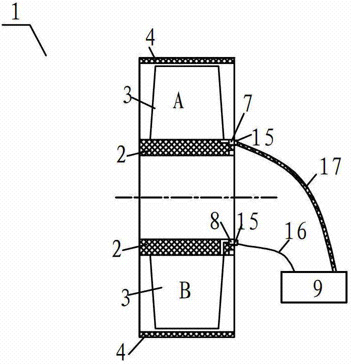
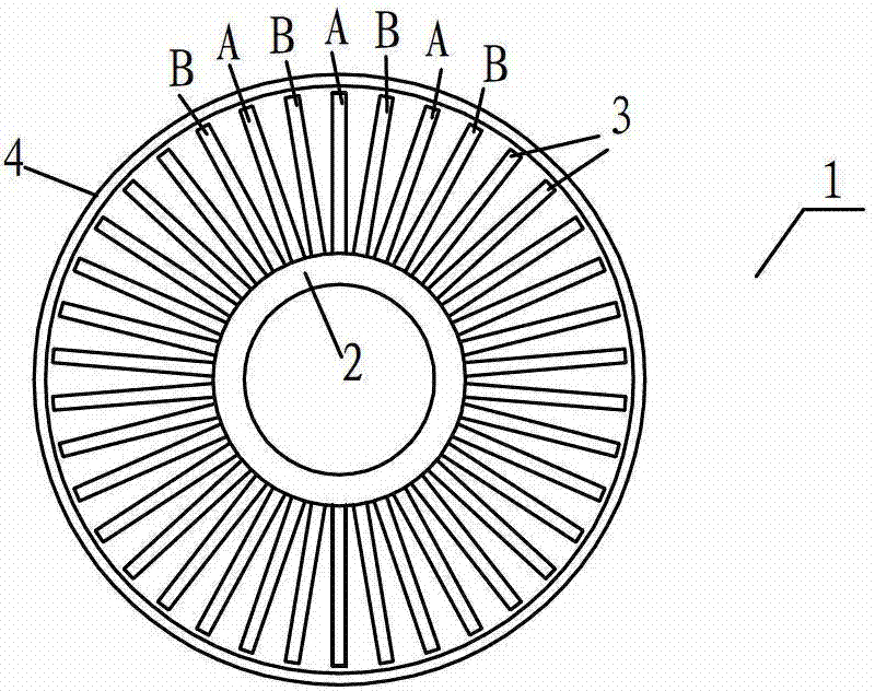
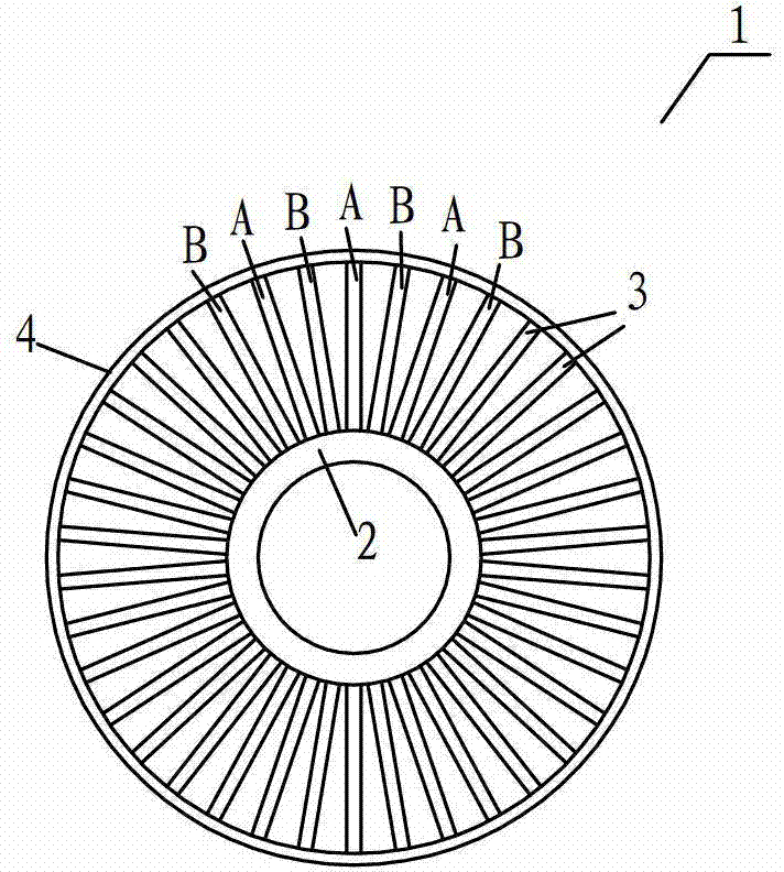
[0076] see Figure 1-Figure 5 , are the front view and the left view of the guide vane or vane 1, respectively. Guide vane or vane 1 includes hub 2 , blade 3 and shroud 4 . One end of the blade 3 is fixed on the hub 2 at certain intervals along the circumferential direction, such as figure 2 shown; or, one end of the blade 3 is fixed on the wheel cover 4 at a certain interval along the circumferential direction, as Figure 4 shown; or, one end of the blade 3 is distributed on the hub 2 at a certain interval along the circumferential direction, and the other end of the blade 3 is fixed on the wheel cover 4 at a certain interval along the circumferential direction at the same time, as image 3 shown; or, the blades 3 are staggered and fixed on the hub 2 or the wheel cover 4 at certain intervals along the circumferential direction, as Figure 5 shown....
PUM
| Property | Measurement | Unit |
|---|---|---|
| thickness | aaaaa | aaaaa |
| clearance rate | aaaaa | aaaaa |
Abstract
Description
Claims
Application Information