Mounting lock catch used for plastic floor

A plastic floor and locking technology, which is applied to floors, buildings, building structures, etc., can solve the problems of broken floor assembly structures, poor control of force, and high manufacturing costs of floor assembly structures.

Inactive Publication Date: 2012-10-24
董春今
View PDF1 Cites 2 Cited by
  • Summary
  • Abstract
  • Description
  • Claims
  • Application Information

AI Technical Summary

Problems solved by technology

However, this patent has the following deficiencies: (1) high cost: since the convex part 1 has a groove that ensures that the end surface of the convex part can be elastically deformed, when the end surface of the convex part can be deformed enough to enter the concave part of the end surface of the concave part, It is necessary to design the groove width and depth of the groove to be larger, so that it is feasible to install the floor smoothly.
However, for the floor of the wooden structure, processing such a groove structure requires high processing technology and directly leads to high manufacturing costs of the floor assembly structure of the structure, and the groove consumes a lot of time during the processing process. Raw materials will also increase the waste of raw materials in the production process, which in turn increases the production cost; (2) Disadvantages in the installation process: During the installation process, the parts that can deform on both sides of the convex part are due to poor elastic-plastic properties of wood. In addition, if the force is not well controlled or the installation position is not properly controlled, there will be problems such as partial fracture of the floor assembly structure.

Method used


Image

  • Mounting lock catch used for plastic floor
  • Mounting lock catch used for plastic floor
  • Mounting lock catch used for plastic floor

Examples


Embodiment 1

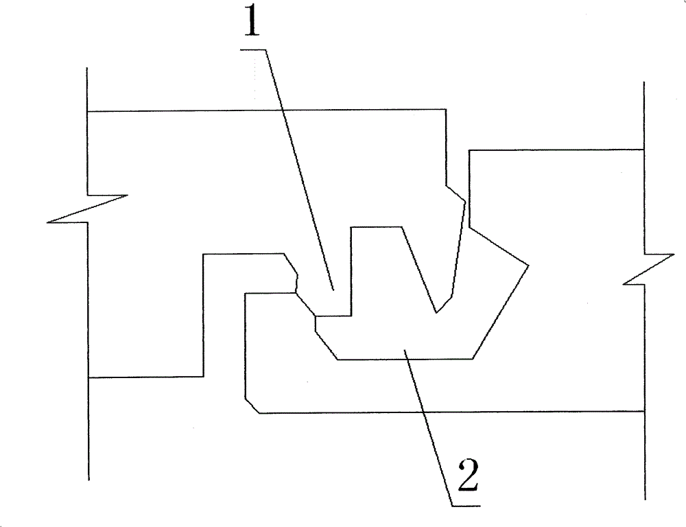
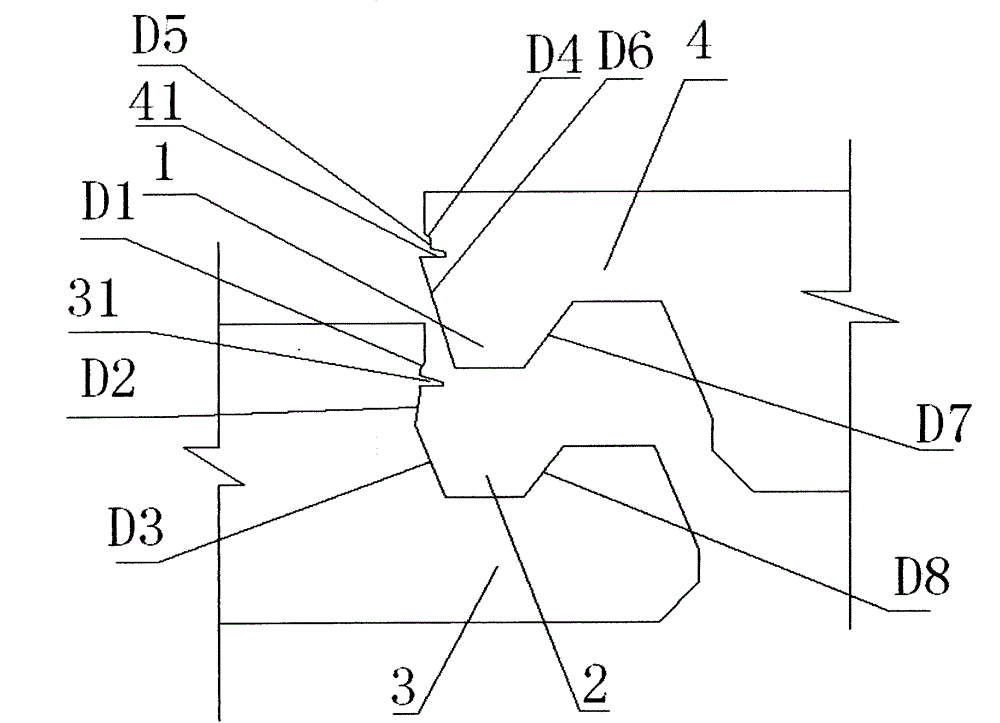
[0024] Such as figure 2 As shown, the left side wall of the recess 2 of the tenon 3 is composed of a vertical facade part, a first chamfer D1 part, a second chamfer D2 part, and a third chamfer D3 part, and the right side of the recess 2 is provided with The female tenon head including the eighth chamfer D8, the left front elevation of the convex part 1 of the male tenon 4 is composed of a vertical facade part, a fourth chamfer D4 part, a fifth chamfer D5 part, and a sixth chamfer D6 Partial composition, the right side of the convex part 1 is provided with a female tenon head placement groove containing the seventh chamfer D7, the left side wall of the female tenon 3 far from the head end of the female tenon is provided with a protruding part 31, and the male tenon A groove 41 having the same shape as the protrusion is provided on the left front elevation of the protrusion 2 of 4, and the maximum width of the front section of the protrusion 31 is less than or equal to the ent...

Embodiment 2

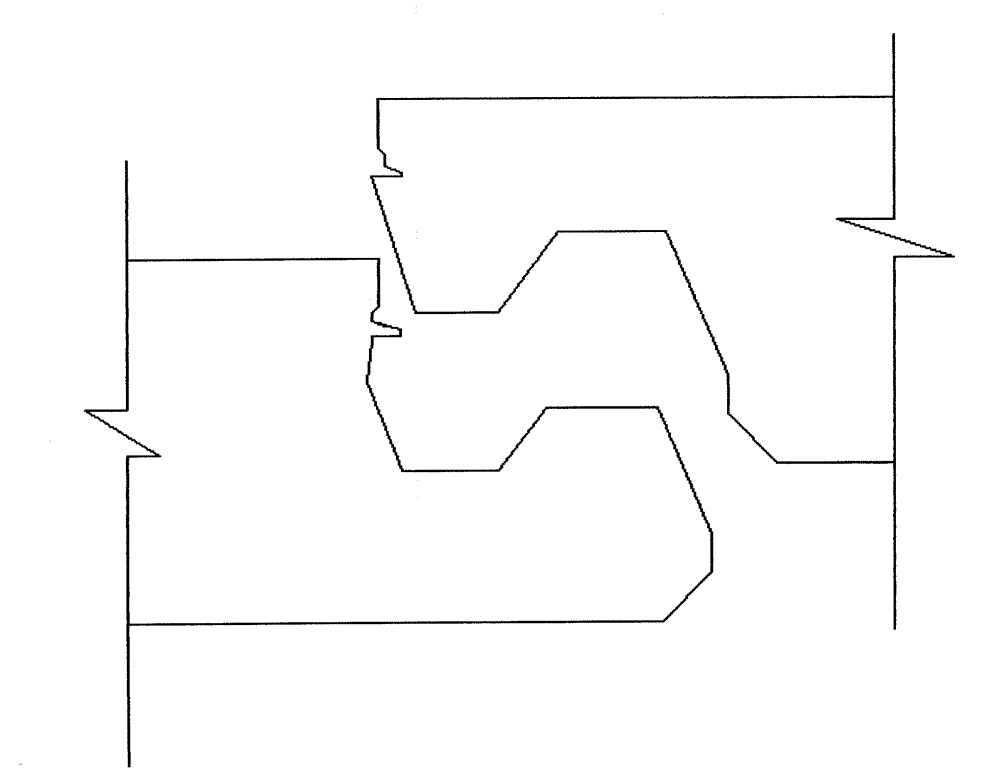
[0032] Such as Figure 6 As shown, in this embodiment, the cross section of the protruding part 31 is triangular, and the cross section of the corresponding groove 41 is concave triangle, and other structural parts are the same as those in the first embodiment.

Embodiment 3

[0034] Such as Figure 7 As shown, in this embodiment, the section of the protruding part 31 is semicircular, and the section of the corresponding groove 41 is semicircular, and other structural parts are the same as those of the first embodiment.

[0035] To sum up, the cross-sectional shapes of the protruding part 31 and the groove 41 are not limited to the above three types, and different shapes can be set according to the needs. direction displacement.


PUM


Abstract

The invention discloses a mounting lock catch used for a plastic floor, comprising a male tenon arranged at one side of the floor and a female tenon, wherein the male tenon is composed of a convex part end face provided with a convex part; the female tenon is composed of a concave part end face provided with a concave part; the side wall of the female tenon, which is far from a tenon head, is provided with a projecting part; the front end of the tenon head of the male tenon is provided with a groove which is the same with the projecting part in the shape; the maximum width of the front section of the projecting part is less than or equal to the inlet width of the front section of the groove; the projecting part is arranged at a second chamfer on the side wall of the female tenon; and the horizontal central axis of the groove and the projecting part is the same in height with the height between surface layers of the floor. The mounting lock catch disclosed by the invention has the beneficial effects that (1) the projecting part arranged on the side wall of the female tenon is matched with the groove which is arranged on the side wall of the male tenon and is the same in shape with the projecting part, and the floor can be quickly mounted in a vertical plane while the floor is ensured not to displace in the vertical direction; and (2) the problem that the floor is damaged due to an assembled structure part in a mounting process can be avoided.

Description

technical field [0001] The invention relates to a floor, in particular to a mounting buckle for a plastic floor. Background technique [0002] Wooden floors are often assembled with a tenon and tenon-groove structure. The installation method of this structure is simple, but the connection between the tenon and tenon-groove is easy to cause the floors to loosen due to the interference of external force or temperature and other related factors during use. This will affect the aesthetics and practicality of the floor. [0003] Chinese utility model patent CN2926380Y discloses a floor board and a floor system, see figure 1 As shown, the floor board includes a convex end surface with a convex portion 1 and a concave end surface with a concave portion 2, and the two cooperate to form an assembled structure. When installing, put the convex part of one floor board on the concave part of another floor board, and then apply pressure in the direction perpendicular to the upper surfac...

Claims


Application Information

Patent Timeline
Patent Type & Authority Applications(China)
IPC IPC(8): E04F15/10
Inventor 董春今
Owner 董春今
Why Eureka
Try Eureka