

Coordinated silent period with sounding reference signal (SRS) configuration
A technology for sounding reference signals and silent periods, applied in the field of interference management, to solve problems such as degrading downlink and uplink performance
- Summary
- Abstract
- Description
- Claims
- Application Information
AI Technical Summary
Problems solved by technology
Method used
Image

Examples
Embodiment Construction
[0023] The detailed description, given below in conjunction with the accompanying drawings, is intended as a description of various configurations and is not intended to represent the only configurations that may be used to implement the concepts described herein. The detailed description includes specific details in order to provide a thorough understanding of various concepts. However, one skilled in the art will recognize that the concepts may be practiced without these specific details. In some instances, well-known structures and components are shown in block diagram form in order to avoid obscuring the concepts.
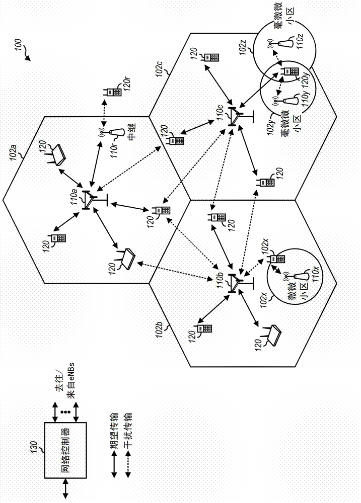
[0024] The techniques described herein can be used in various wireless communication networks such as Code Division Multiple Access (CDMA) networks, Time Division Multiple Access (TDMA) networks, Frequency Division Multiple Access (FDMA) networks, Orthogonal FDMA (OFDMA) networks, single carrier FDMA (SD-FDMA) networks and more. The terms "network" and "syste...
PUM
 Abstract
Description
Claims
Application Information