A motor, fan and cyclonic separation apparatus arrangement

一种分离装置、旋风分离器的技术,应用在马达风扇组件的安装、电设备的安装、化学仪器和方法等方向,能够解决分离效率低分离效率等问题,达到紧凑旋风式分离装置的效果

Inactive Publication Date: 2013-04-17
BLACK & DECKER INC
View PDF13 Cites 9 Cited by
  • Summary
  • Abstract
  • Description
  • Claims
  • Application Information

AI Technical Summary

Problems solved by technology

The separation efficiency of the first cyclonic separation unit is lower than the separation efficiency of the second cyclonic separation unit

Method used


Image

  • A motor, fan and cyclonic separation apparatus arrangement
  • A motor, fan and cyclonic separation apparatus arrangement
  • A motor, fan and cyclonic separation apparatus arrangement

Examples


Embodiment Construction

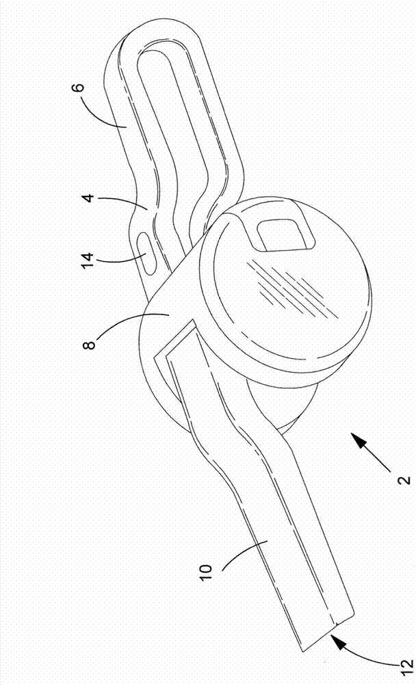
[0080] refer to figure 1 , which shows a first embodiment of a hand-held vacuum cleaner 2 comprising: a main body 4; a handle 6 connected to the main body 4; a cyclonic separation device 8 mounted on the main body and transversely across the main body; and a dirty air channel 10 having a dirty air inlet 12 at one end. The vacuum cleaner includes: an electric motor that engages a fan for generating air flow through the vacuum cleaner; and a rechargeable battery (not shown) Provides electrical energy to the motor when electrically connected to the motor.

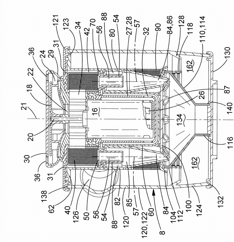
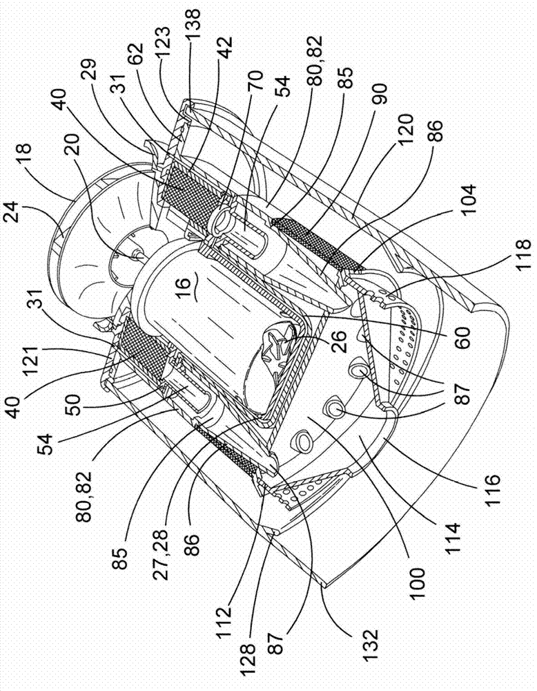
[0081] refer to Figure 2 to Figure 8 , which shows a structure including a motor 16, a fan 18 and a cyclonic separation device 8. The electric motor has a drive shaft 20 with a central axis 21 . The fan is a centrifugal fan 18 with an axial inlet 22 facing the motor and a tangential outlet 24 . The diameter of the fan is 68mm. The fan is mounted on the drive shaft that sits on top of the motor. In use, an electric moto...


PUM


Abstract

A motor, fan and cyclonic separation apparatus arrangement for a vacuum cleaner (2,602,702,802) comprising: a motor coupled to a fan for generating air flow; and a cyclonic separation apparatus located in a path of the air flow generated by the fan. The cyclonic separation apparatus comprises: a plurality of cyclones (84,284) each with an air inlet port (88,288) and an air outlet port (56,256); and a cooling air flow path (61a,61b) . The motor comprises a permanent magnet brushless motor, a switched reluctance motor or a flux switching motor. The fan has an outer diameter the same or less than the diameter of the motor. The plurality of cyclones, the motor and the fan are arranged in a circular array about a central axis (21,321) of the cyclonic separation apparatus. The arrangement comprises a baffle for directing air flow from the fan out of the circular array. The motor is located in the cooling air flow path.

Description

technical field [0001] The present invention relates to the structure of electric motor, fan and cyclone type separating device. The invention relates particularly, but not exclusively, to the construction of electric motors, fans and cyclonic separation devices for use in vacuum cleaners. Background technique [0002] Vacuum cleaners are well known for collecting dust and dirt, but wet and dry variant vacuum cleaners capable of collecting liquids are also known. Typically vacuum cleaners are intended for use in residential environments, but they may also be used in other environments such as construction sites or gardens. Typically, they are powered by electricity and thus include: an electric motor; a fan connected to the output shaft of the motor; an inlet for dirty air; an outlet for clean air; and for dust, dirt (and possibly liquids) collection chamber. Power for the motor may be provided by mains power, in which case the vacuum cleaner will also include a power cor...

Claims


Application Information

Patent Timeline
Patent Type & Authority Applications(China)
IPC IPC(8): A47L9/16A47L9/28A47L9/00A47L9/12
CPCA47L5/22A47L9/1633A47L9/1641A47L9/22Y10S55/03
Inventor 凯文·史密斯
Owner BLACK & DECKER INC
Why Eureka
Try Eureka