An Optical Time Division Multiplexing Device Based on Aperture-Limited Temporal Lens

A technology of time lens and aperture, which is applied in the field of high-speed optical communication, can solve problems affecting stability, etc., and achieve the effects of stable performance, simple control, and high resolution and multiplexing

Inactive Publication Date: 2016-01-20
TSINGHUA UNIV
View PDF5 Cites 2 Cited by
  • Summary
  • Abstract
  • Description
  • Claims
  • Application Information

AI Technical Summary

Problems solved by technology

In the 2012 OFC conference article "160Gbaud / sto40Gbaud / sOTDM-DQPSKDe-multiplexBasedonaDualParallelMach-ZehnderModulator", it is proposed to use dual-parallel MZM, the multiplexed signal is divided into two branches, and then passes through the Mach-Zehnder modulator, and then interferes to achieve 160Gb / s to 40Gb / s error-free demultiplexing, the power penalty is about 0.6dB, but the system needs to apply 3 DC biases, too many DC biases affect its stability

Method used


Image

  • An Optical Time Division Multiplexing Device Based on Aperture-Limited Temporal Lens
  • An Optical Time Division Multiplexing Device Based on Aperture-Limited Temporal Lens
  • An Optical Time Division Multiplexing Device Based on Aperture-Limited Temporal Lens

Examples


Embodiment

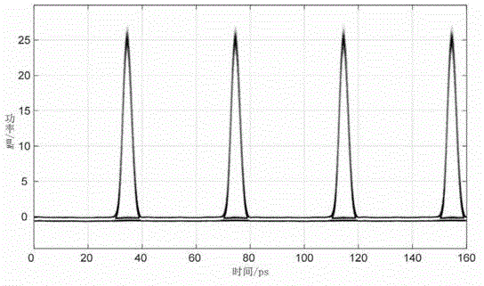
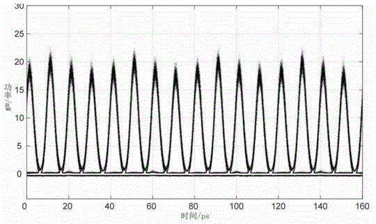
[0044] This embodiment can realize 100Gb / s-25Gb / s signal demultiplexing. Four 25G signals with a pulse width of about 4 ps are multiplexed to 100G as shown in Figure 3(a), as shown in Figure 3(b).

[0045] The structure of this embodiment is as figure 2 As shown, each component adopts the above implementation manner.

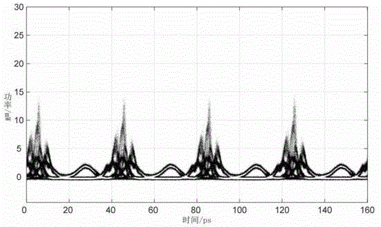
[0046] The working process of this embodiment is: the multiplexed signal is connected to the phase modulator 2 after passing through the polarization controller 1 , and the modulation factor of the phase modulator 2 in this embodiment is about 2π. After the divergence time lens composed of phase modulator 2 and 350m single-mode fiber (dispersive medium unit 3), the non-target signal converges and fully squeezes to the edge of the frame clock period, and separates from the target signal, as shown in Figure 3(c). After passing through the intensity modulator 4 (optical switch window), a target signal is extracted, as shown in Figure 3(d). The demultiplexed sig...


PUM


Abstract

The invention relates to an optical time-diversion multiplexing device based on an aperture limited time lens and belongs to the technical field of high-speed optical communication. The optical time-diversion multiplexing device comprises a polarization controller, a phase modulator, a dispersive medium unit, an intensity modulator, a dispersion compensation unit, a frame clock source, a power divider, two phase shifters and two power amplifiers, wherein the polarization controller, the phase modulator, the dispersive medium unit, the intensity modulator and the dispersion compensation unit are sequentially and optically connected, the frame clock source, the first phase shifter, the power divider and the second phase shifter are sequentially connected, the input end of the first power amplifier and the input end of the second power amplifier are connected with the output end of the power divider and the output end of the second phase shifter respectively, and the output end of the first power amplifier and the output end of the second power amplifier are connected with the phase modulator and the intensity modulator respectively. The optical time-diversion multiplexing device based on the aperture limited time lens has the advantages of being simple in structure, stable in performance and low in power penalty.

Description

technical field [0001] The invention belongs to the technical field of high-speed optical communication, in particular to an optical time division multiplexing device. Background technique [0002] Optical time division multiplexing is one of the key technologies in the optical time division multiplexing (OTDM) communication system, and it is also a difficult technology in the optical time division communication system. There are two main types of optical time division multiplexing technologies currently used: all-optical demultiplexing and electro-optical demultiplexing. Among them, all-optical demultiplexing is an optical control switch technology realized by the nonlinear effect of nonlinear materials. Commonly used nonlinear devices include highly nonlinear optical fiber (HNLF), semiconductor optical amplifier (SOA), silicon waveguide (SiliconWaveguide) and periodic Polarized lithium niobate (PPLN). The typical structure of the demultiplexer using highly nonlinear opti...

Claims


Application Information

Patent Timeline
Patent Type & Authority Patents(China)
IPC IPC(8): H04J14/08G02F2/00
Inventor 霍力姜向宇邢燕飞娄采云
Owner TSINGHUA UNIV
Why Eureka
Try Eureka