Thermally conductive device for absorber and method of making the same

An absorber and solar collector technology, which is applied in the field of manufacturing heat conduction devices, can solve problems such as different cross-sections or thicknesses, and achieve the effect of low cost

Inactive Publication Date: 2016-09-21
ROBERT BOSCH GMBH
View PDF11 Cites 0 Cited by
  • Summary
  • Abstract
  • Description
  • Claims
  • Application Information

AI Technical Summary

Problems solved by technology

[0006] The problem when producing heat conducting devices by means of blow molding is that the cavities or ducts in the collecting pipe and in the absorption area have different cross-sections or thicknesses

Method used


Image

  • Thermally conductive device for absorber and method of making the same
  • Thermally conductive device for absorber and method of making the same
  • Thermally conductive device for absorber and method of making the same

Examples


Embodiment Construction

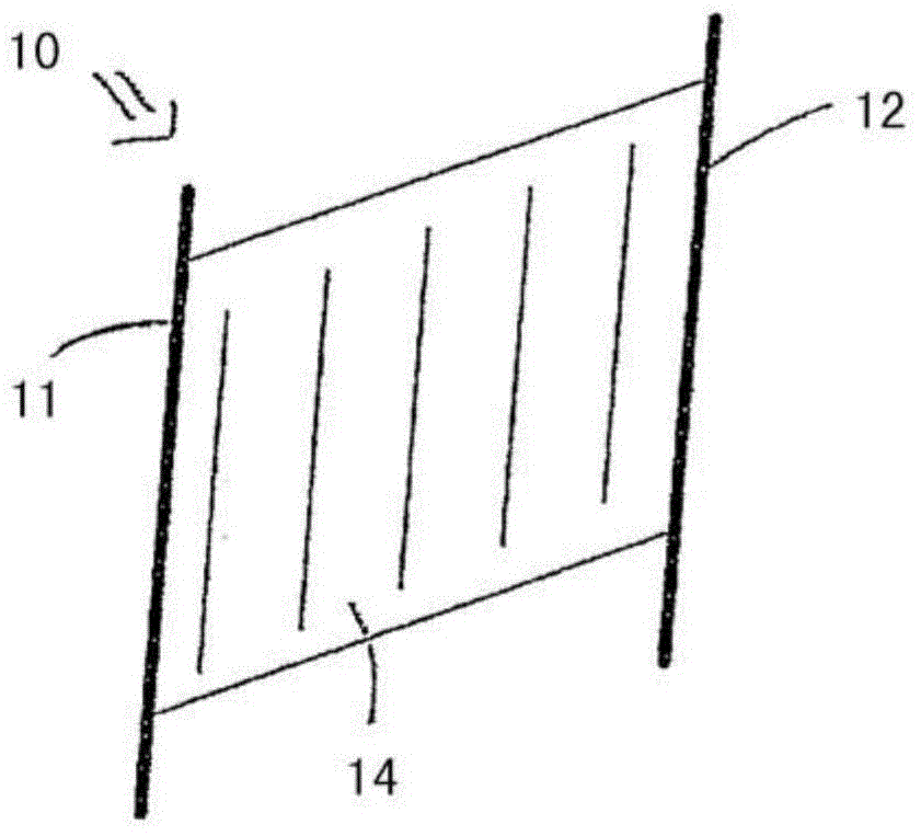
[0030] figure 1 Shown is a heat conduction device 10 according to the invention for the flow of a heat transfer medium of a planar absorber of a solar collector, said heat conduction device comprising a first collecting tube 11 for introducing the heat transfer medium and a A second collecting pipe 12 for the heat transfer medium, wherein the collecting pipes 11 , 12 each have at least one lateral opening not shown in this figure, through which the collecting pipe communicates with a likewise not shown Hollow chamber connection. The hollow chamber is formed in a one-piece plastic body 14 in which the two collecting tubes 11 , 12 are accommodated.

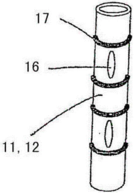
[0031] figure 2 A side view of one collecting pipe 11 , 12 of the heat conducting device according to the invention is shown. The collecting tubes 11 , 12 have two lateral openings 16 . The lateral openings 16 are each designed as elongated holes in this example. However, any other configuration is also conceivable as long as ...


PUM


Abstract

The invention relates to a heat-conducting device (10) for accommodating a heat-transfer medium for a planar absorber of a solar thermal collector, comprising a first header (11) for feeding the heat-transfer medium and a second header (12) for removing the heat-transfer medium, wherein the headers (11, 12) each have at least one lateral opening (16), by means of which said headers are connected to a cavity (13), wherein the cavity (13) is formed in a one-piece plastic body (14), and wherein the two headers (11, 12) are enclosed in the plastic body (14). The invention further relates to a method for producing such a heat-conducting device (10).

Description

technical field [0001] The invention relates to a heat conducting device for an absorber and a method for producing the heat conducting device. Background technique [0002] Solar collectors are generally known. They usually have a relatively flat and large-area absorber plate that receives energy in the form of light, converts it into heat and releases it to a heat-carrying medium that flows through the absorber plate . [0003] Various embodiments of such solar collectors are described in the prior art. Usually, the heat conduction device with multifaceted structure has a first collecting pipe for introducing the heat transfer medium and a second collecting pipe for leading out the heat transfer medium connected to the first collecting pipe through one or more hollow chambers or pipes. Two collecting pipes, wherein in particular the cavities or ducts are in heat-conducting contact with the absorber plate and thus form the actual absorption region of the heat-conducting ...

Claims


Application Information

Patent Timeline
Patent Type & Authority Patents(China)
IPC IPC(8): F24J2/20F24J2/46B29C49/42F24S10/50
CPCB29C49/4247F24S10/501F24S10/506F24S80/30F28F3/14F28F9/0243F28F21/065Y02E10/44
Inventor U·克莱门特M·菲滕
Owner ROBERT BOSCH GMBH
Why Eureka
Try Eureka