Electromagnetic Actuating Device

一种调整设备、电磁的技术,应用在机械设备、电路、磁体等方向,能够解决提高结构或安装费用等问题

Active Publication Date: 2014-08-06
ETO MAGNETIC GMBH
View PDF5 Cites 4 Cited by
  • Summary
  • Abstract
  • Description
  • Claims
  • Application Information

AI Technical Summary

Problems solved by technology

[0004] It is therefore known from the prior art that adjustment tasks requiring a plurality of actuators are carried out by means of actuators which are fixed or arranged independently of each other, which leads to increased construction or installation costs, and generally only a limited compactness of the entire device sex
[0005] Due to today's requirements for the use of multiple push rod units, these push rod units are closely adjacent to each other and often only allow a predetermined maximum distance from each other, which makes the above problems more acute; Actuators can not possibly or only limitedly solve this problem

Method used


Image

  • Electromagnetic Actuating Device
  • Electromagnetic Actuating Device
  • Electromagnetic Actuating Device

Examples


Embodiment Construction

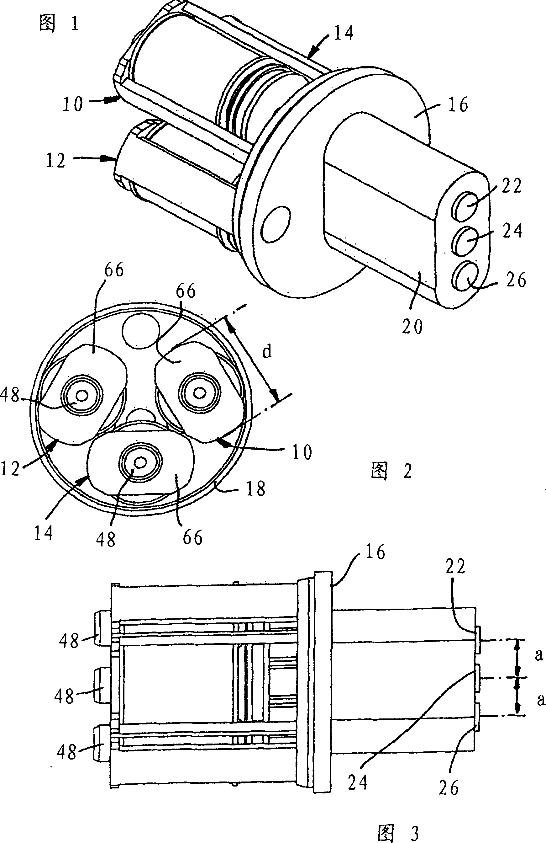
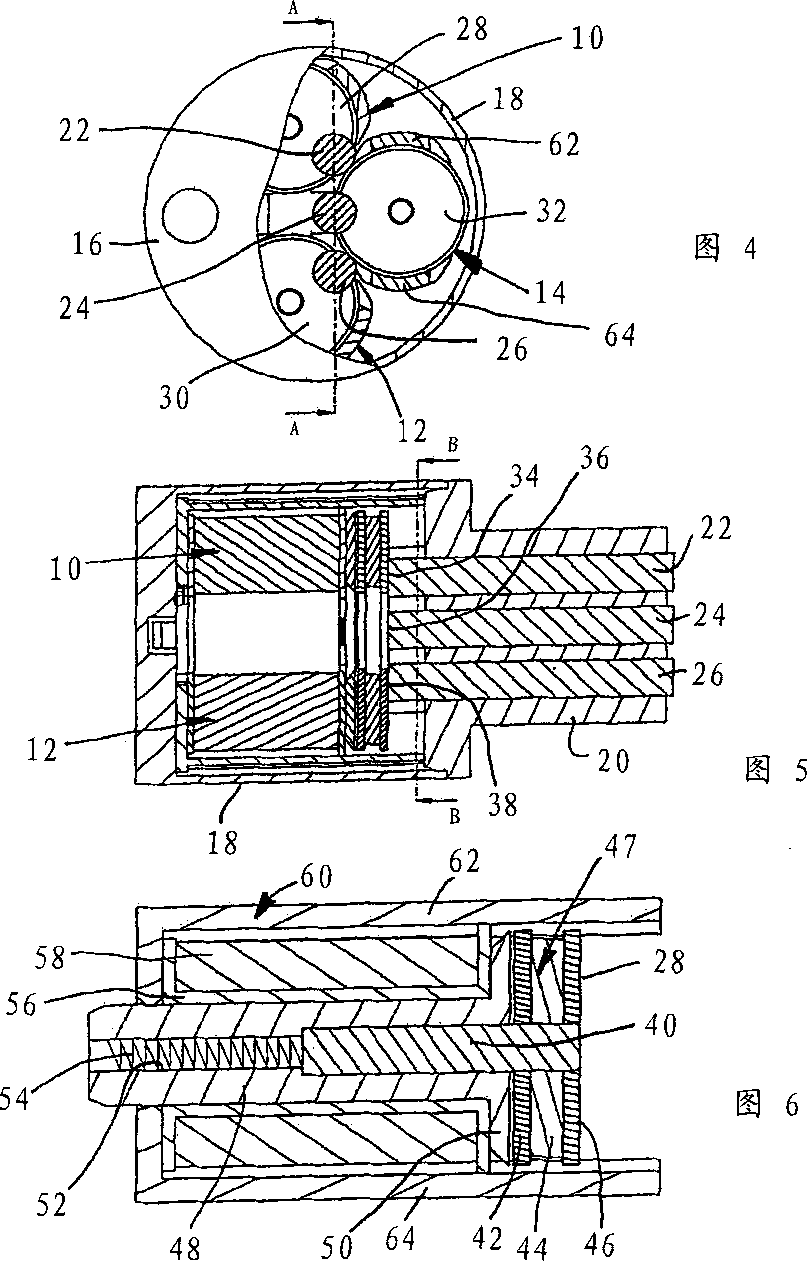
[0032] Figures 1 to 3 For the first embodiment, it is shown how the three actuators 10, 12, 14 are distributed in a housing (only a circular housing cover 16 as a yoke is shown), so that the actuators 10 to 14 abut against In the housing jacket 18 ( figure 1 and 3 Not shown) on the inner wall of the hollow cylinder. An active-side flat housing section 20 is arranged on the housing cover (yoke) 16, which has three through-holes lying side by side in a plane of extension for guiding three pusher units 22, 24, 26, which are arranged according to They are axially parallel mounted in the illustrated manner and selectively actuatable by the associated actuators 10, 12, 14 in the manner to be explained below.

[0033]Here, the maximum diameter d of an actuator 10 to 14 is about 17 mm when the external diameter of the housing is typically 40 mm; therefore, according to the unit connected downstream, in this embodiment the installation of the camshaft control device of the internal...


PUM

PropertyMeasurementUnit
diameteraaaaaaaaaa

Abstract

The invention relates to an electromagnetic actuating device comprising a plurality of electromagnetic actuation units (10, 12, 14), which can be selectively controlled for exerting an actuating forceon a corresponding plurality of elongated tappet units (22, 24, 26) that are supported axially parallel, wherein the actuation units are provided in a common housing (18, 20; 78, 82) along the actuating direction axially parallel to each other, and form a contact surface that is at least planar in some sections and can be axially moved in the actuating direction at each associated engagement endfacing the tappet units.; A face (34, 36, 38) on the engagement side of each of the tappet units interacts with the engagement surface (28, 30, 32), wherein at least one of the plurality of tappet units sits eccentrically and / or with only a partial surface, with the face thereof on the engagement side, on the engagement surface of the associated actuation unit, particularly adheres to it magnetically.

Description

[0001] This application is a divisional application of the original application with an international filing date of June 19, 2008, a national application number of 200880021134.4, and an invention title of "Electromagnetic Adjusting Equipment". technical field [0002] The invention relates to an electromagnetic adjustment device according to the preamble of claim 1 . The prior art concerning such devices is well known, and they are used, for example, in connection with internal combustion engines for various adjustment tasks. Background technique [0003] Due to the limited installation space at the place of use, it is often necessary to implement an adjustment device of this type in a sufficiently compact manner for the specific adjustment task with several (typically selectively ie independently controllable) actuator units, so that a On the one hand, a sufficient electromagnetic function is ensured (for example with respect to the necessary adjustment strokes and reacti...

Claims


Application Information

Patent Timeline
Patent Type & Authority Applications(China)
IPC IPC(8): H01F7/126F01L1/34
CPCF01L13/0036H01F2007/1692F01L2013/0052F01L2820/031F01L2101/00H01F7/1646H01F7/126F01L2820/01F01L2301/00
Inventor 托马斯·戈尔兹托马斯·希普
Owner ETO MAGNETIC GMBH
Why Eureka
Try Eureka