
Ducted Thrust Vectoring Applicable to Small Unmanned Aerial Vehicles
A small unmanned aerial vehicle, vector thrust technology, which is applied in the directions of power plant, aircraft power plant components, and aircraft parts, etc., can solve the problem of no practical use of unmanned aerial vehicles, and achieve the conditions of low cost, light weight and technical implementation. mature effect
- Summary
- Abstract
- Description
- Claims
- Application Information
AI Technical Summary
Problems solved by technology
Method used
Image


Examples
Embodiment Construction
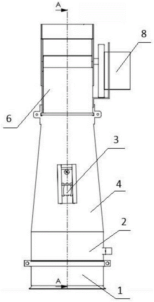
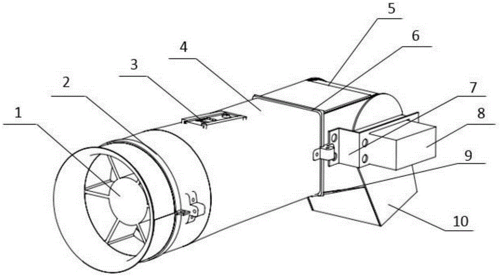
[0018] See attached figure 1 , 2 , 3, the ducted vector thrust device suitable for small unmanned aerial vehicles, it includes: the thrust generating device for generating the airflow, the vectoring nozzle assembly for changing the direction of the airflow and the connecting thrust generating device and the vectoring nozzle assembly deflector;
[0019] The thrust generating device is a ducted fan 1;
[0020] The diversion device includes: a pipeline 4 and a circular fixing ring 2 and a square fixing ring 6 installed at the front and rear ends of the pipeline 4; the front end port of the pipeline 4 is circular, the rear end port is square, and the middle part is contracted and smoothly transitioned; The middle part of 4 is provided with a lead window 3, which is used to lead out the power line and oil pipe of the ducted fan; the inner wall of the square fixing ring 6 is provided with an upper slideway 13 and a slideway 14;
[0021] See attached Figure 4 , 5 , the vector n...
PUM
 Abstract
Description
Claims
Application Information