
Bypass type vector thrust device suitable for small unmanned aerial vehicle

A small unmanned aerial vehicle, vector thrust technology, applied in the direction of aircraft power plant, aircraft power plant components, aircraft parts, etc., can solve the problem of unmanned aerial vehicles without practical use, and achieve low cost, light weight, and technical implementation conditions mature effect

Active Publication Date: 2014-09-17
BEIJING INSTITUTE OF TECHNOLOGYGY
View PDF5 Cites 16 Cited by
  • Summary
  • Abstract
  • Description
  • Claims
  • Application Information

AI Technical Summary

Problems solved by technology

While thrust vectoring has been used extensively in aviation, it has no practical use in UAVs

Method used


Image

  • Bypass type vector thrust device suitable for small unmanned aerial vehicle
  • Bypass type vector thrust device suitable for small unmanned aerial vehicle
  • Bypass type vector thrust device suitable for small unmanned aerial vehicle

Examples


Embodiment Construction

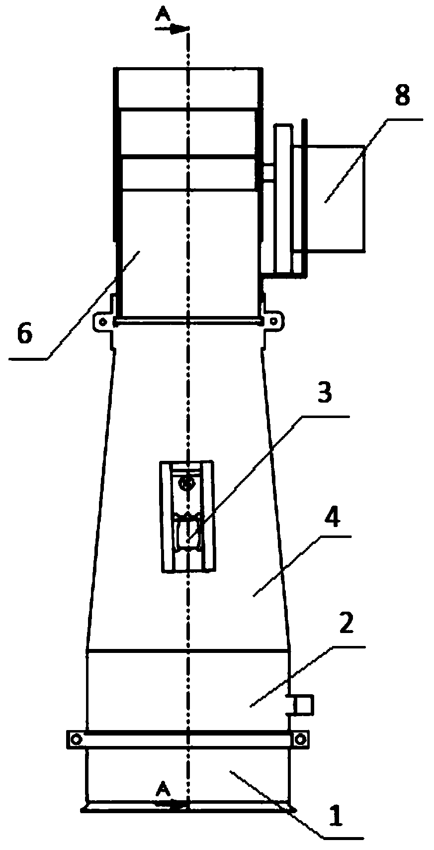
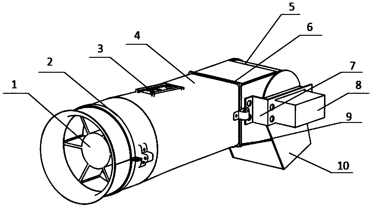
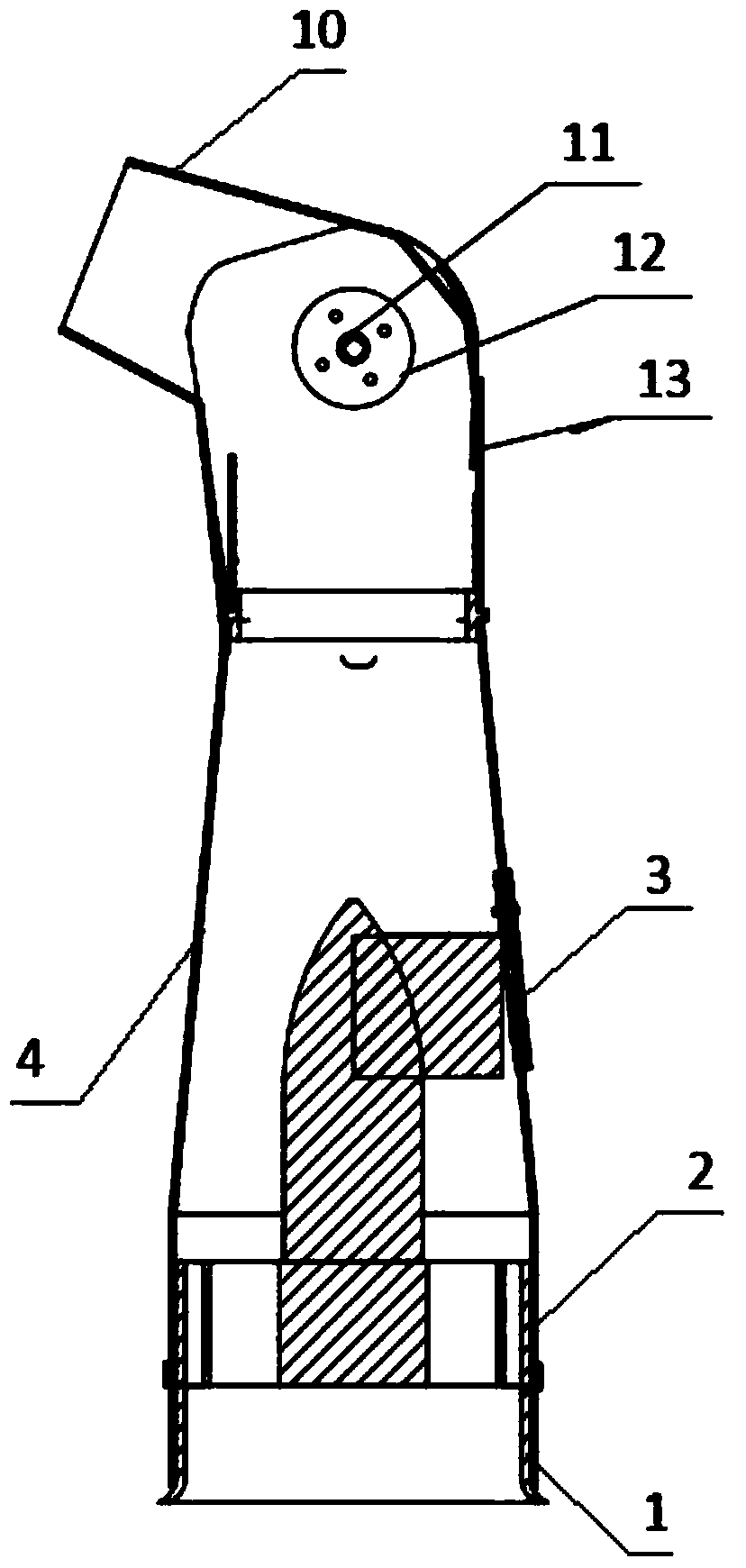
[0018] See attached figure 1 , 2 , 3, the ducted vector thrust device suitable for small unmanned aerial vehicles, it includes: the thrust generating device for generating the airflow, the vectoring nozzle assembly for changing the direction of the airflow and the connecting thrust generating device and the vectoring nozzle assembly diversion device;

[0019] The thrust generating device is a ducted fan 1;

[0020] The diversion device includes: a pipeline 4 and a circular fixing ring 2 and a square fixing ring 6 installed at the front and rear ends of the pipeline 4; the front end port of the pipeline 4 is circular, the rear end port is square, and the middle part is contracted and smoothly transitioned; The middle part of 4 is provided with a lead window 3, which is used to lead out the power line and oil pipe of the ducted fan; the inner wall of the square fixing ring 6 is provided with an upper slideway 13 and a slideway 14;

[0021] See attached Figure 4 , 5 , the v...


PUM


Abstract

The invention relates to a vector thrust device, in particular to a bypass type vector thrust device. The bypass type vector thrust device is suitable for small unmanned aerial vehicles, and adopts the technical scheme that the bypass type vector thrust device comprises a thrust generation device, a vector nozzle assembly and a flow guide device, wherein the thrust generation device is used for generating air flow, the vector nozzle assembly is used for changing the direction of the air flow, the thrust generation device is a bypass fan (1), the flow guide device comprises a pipeline (4), circular fixing rings (2) and square fixing rings (6), the circular fixing rings (2) and the square fixing rings (6) are arranged at the front and back ends of the pipeline (4), and the vector nozzle assembly comprises a rudder (8), a turntable (12) and a tail nozzle port (10). The bypass type vector thrust device has the advantages that the vertical deflection of the tail nozzle port is realized by controlling a steering device to rotate, the vertical landing and takeoff and the hovering of the small unmanned aerial vehicle are realized, and the unmanned aerial vehicle is guaranteed to realize maneuvering flight at low speed and large angle of attack, and is controlled to normally fly by utilizing the vector thrust to provide additional operation torque when the operation of rudder surface nearly fails.

Description

technical field [0001] The invention relates to a vector thrust device, in particular to a ducted vector thrust device. Background technique [0002] With the rapid development of UAV technology in the world, a large number of fixed-wing UAVs and multi-axis rotor UAVs have appeared. The take-off and landing of fixed-wing UAVs requires a certain sliding distance, has strict requirements on the runway, has limited maneuverability, and cannot achieve ultra-low-speed cruise. Although the multi-axis rotor UAV can take off and land vertically, it has disadvantages such as slow flight speed, short range, low flight altitude, and poor survivability. So far, the take-off and landing methods of existing UAVs have great limitations, and cannot cope well with various emergencies. How to effectively improve the take-off and landing performance and maneuverability of UAVs has become an urgent problem to be solved. [0003] At present, the United States and Russia use thrust vectoring t...

Claims


Application Information

Patent Timeline
Patent Type & Authority Applications(China)
IPC IPC(8): B64D29/06B64C7/02
Inventor 唐胜景周小陈李博刘真畅李震陈天悦
Owner BEIJING INSTITUTE OF TECHNOLOGYGY
Learn More