Supercharge Your Innovation With Domain-Expert AI Agents!

De-humidifying system

A technology for towers and wind turbines, used in machines/engines, mechanical equipment, wind power generation, etc.

Active Publication Date: 2014-12-17
SIEMENS GAMESA RENEWABLE ENERGY AS
View PDF5 Cites 10 Cited by
  • Summary
  • Abstract
  • Description
  • Claims
  • Application Information

AI Technical Summary

Problems solved by technology

[0010] This shows the disadvantage of requiring energy to operate a dehumidification system

Method used


Image

  • De-humidifying system
  • De-humidifying system
  • De-humidifying system

Examples


Embodiment Construction

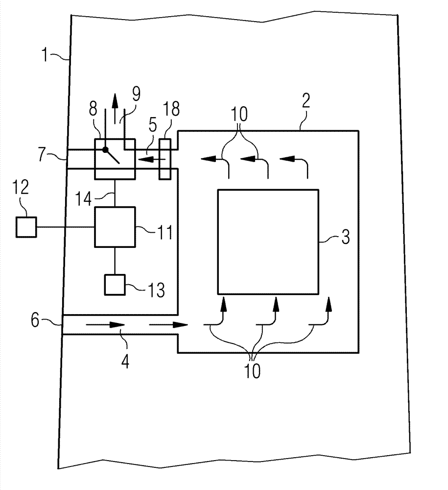
[0072] figure 1 A dehumidification system is shown.

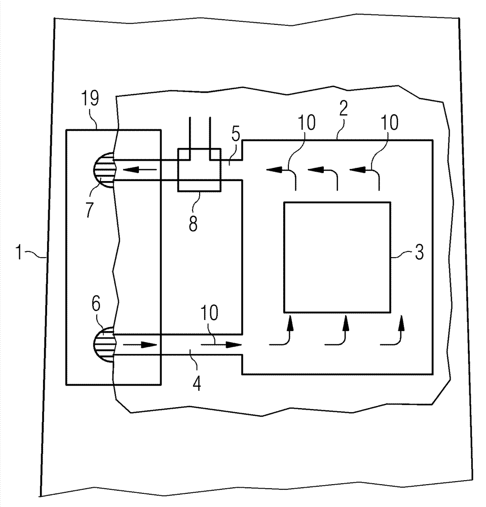
[0073] figure 1 A dehumidification system of a wind turbine tower is shown. The tower 1 comprises a chamber 2 with electrical installations 3 emitting waste heat. The electrical device 3 is cooled by the air flow 10 .

[0074] A first pipe 4 connects the interior of the chamber 2 to the exterior of the tower 1 . The first pipe 4 is connected to a through hole 6 in the wall of the tower 1 . The first duct 4 allows air to flow from outside the tower 1 into the chamber 2 .

[0075] A second pipe 5 connects the interior of the chamber 2 to the exterior of the tower 1 . The second pipe 5 is connected to a through hole 7 in the tower wall. The second duct 5 allows air to flow from the chamber 2 to the outside of the tower 1 .

[0076] Air 10 flows into the chamber 2 through the through hole 6 and the first tube 4 . In the chamber 2 the air is warmed up by means of electrical means 3 . The heated air flows along the seco...


PUM


Abstract

The invention relates to a de-humidifying system of a wind turbine. In a wind turbine tower de-humidifying system the tower comprises a chamber in its interior. The chamber comprises an electrical arrangement that admits waste heat. A first tube connects the interior of the chamber to the exterior of the tower, to allow air from the exterior of the tower to flow into the chamber. A second tube connects the interior of the chamber to the exterior of the tower, to allow air from inside the chamber to flow to the exterior of the tower. A valve is arranged in the second tube to open a passage between the second tube and the interior of the tower, to allow air from the chamber to flow into the tower.

Description

technical field [0001] The present invention relates to dehumidification systems for wind turbines. Background technique [0002] A wind turbine includes a wind turbine rotor with rotor blades. The rotor is attached to the nacelle of the wind turbine. The nacelle is arranged on top of the tower. [0003] Wind turbines are used onshore or offshore. Onshore wind turbines are usually installed close to the coast. In offshore areas and near the coast, the humidity of the ambient air can be quite high. [0004] Due to the humidity and changing temperature of the ambient air, moisture tends to condense on the cold surfaces of the wind turbine. Especially in towers of wind turbines, humidity levels can reach levels where corrosion or mold can form inside the tower. [0005] Such high humidity levels are undesirable as moisture can cause problems for the electrical systems in the tower and the tower itself. [0006] Therefore, it is known to prevent water and moisture from en...

Claims


Application Information

Patent Timeline
Patent Type & Authority Applications(China)
IPC IPC(8): F03D11/00
CPCF05B2270/325F05B2270/324F05B2260/64F03D11/00F03D11/0091F03D11/005F05B2270/323F03D9/002F03D80/00F03D17/00F03D80/80F03D9/25Y02E10/72F03D80/60
Inventor C.M.索伦森
Owner SIEMENS GAMESA RENEWABLE ENERGY AS
Features
  • R&D
  • Intellectual Property
  • Life Sciences
  • Materials
  • Tech Scout
  • Unparalleled Data Quality
  • Higher Quality Content
  • 60% Fewer Hallucinations
Learn More