Plate-fin heat exchanger

A heat exchanger and plate-fin technology, applied in the field of plate-fin heat exchangers, can solve the problems of high manufacturing difficulty and high cost.

Inactive Publication Date: 2015-01-21
无锡协丰节能技术有限公司
View PDF8 Cites 9 Cited by
  • Summary
  • Abstract
  • Description
  • Claims
  • Application Information

AI Technical Summary

Problems solved by technology

Since the fins in the middle and the adjacent two partitions need to be combined into a whole, the plate-fin heat exchanger needs to be m

Method used


Image

  • Plate-fin heat exchanger
  • Plate-fin heat exchanger
  • Plate-fin heat exchanger

Examples


Embodiment Construction

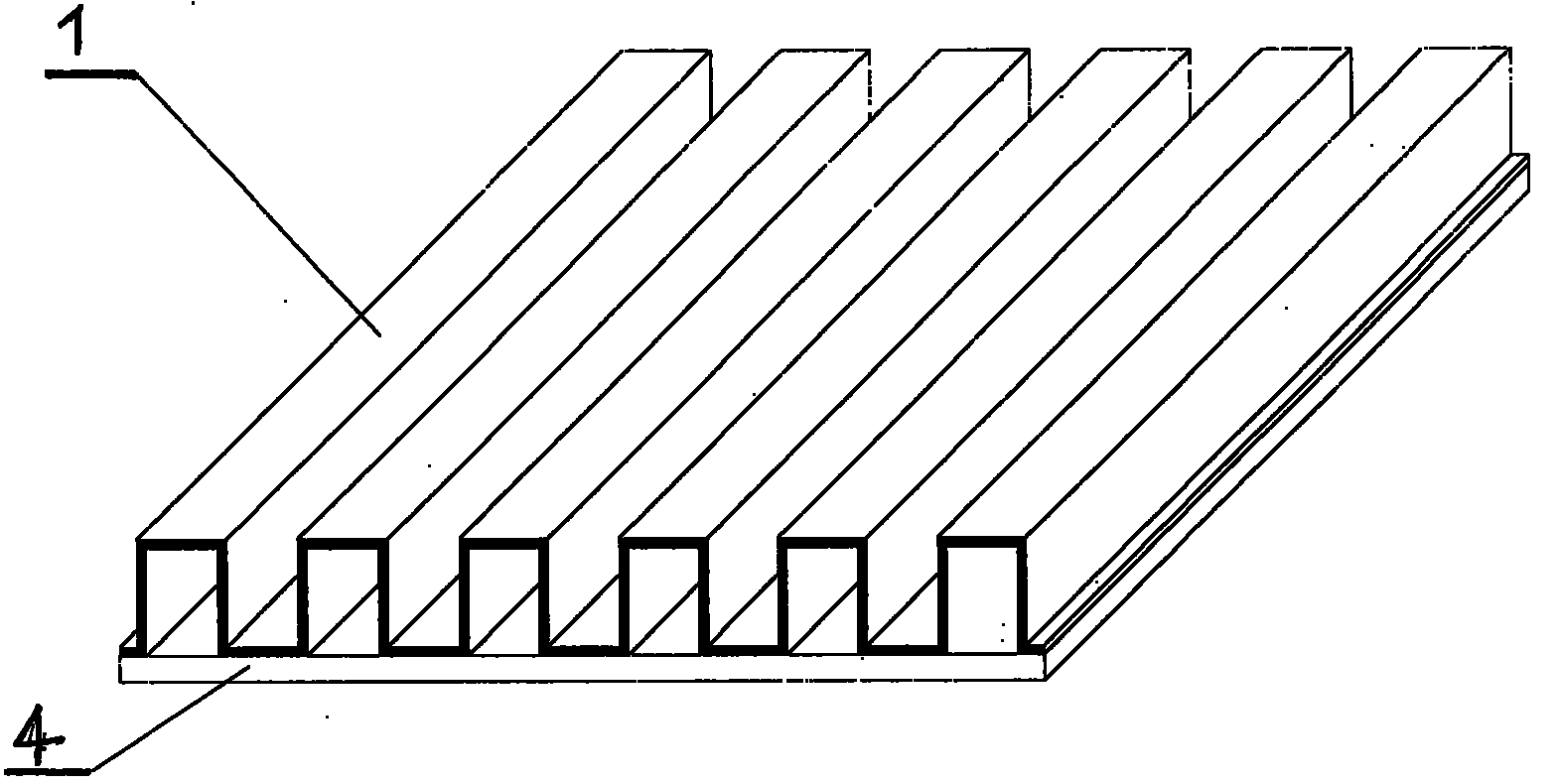
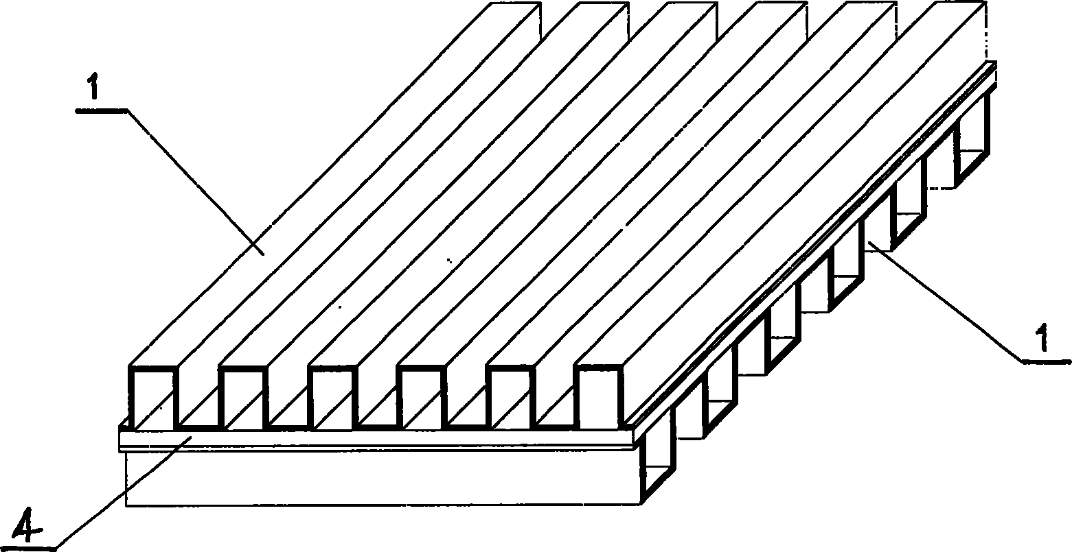
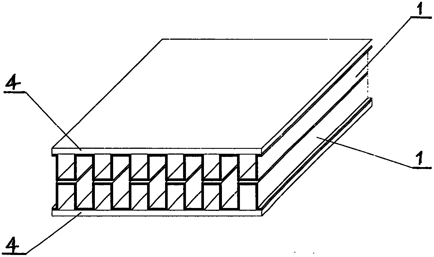
[0014] Figure 4 For a "middle partition-fin structure" (8) figure of the present invention, from Figure 4 It can be seen that the "middle partition-fin structure" (8) is composed of a middle partition (4) and two fins (1) attached to its two sides, and the two fins on the front and back sides of the middle partition (4) The sheets (1) are arranged in a 90-degree cross arrangement; Figure 5 It is the "outer partition-fin structure" (7) figure of the plate-fin heat exchanger of the present invention, from Figure 5 It can be seen that the "outer partition-fin structure" (7) is composed of the outer partition (7) and two fins (1) attached to its two sides; from Figure 4 and Figure 5 It can be seen that the combination of fins (1) and intermediate partitions (4) can be carried out independently, and the combination of each intermediate partition (4) and fins (1) is very clearly visible, which is conducive to inspection. Poor quality is also easy to replace without affecti...


PUM


Abstract

The invention discloses a plate-fin heat exchanger. According to the abstract drawing of the plate-fin drawing, all passageway units of a middle partition plate-fin structure (8) are overlapped and arrayed at intervals in a 90-degree crossing mode, and outer partition plate-fin structures (7) are arranged on the two outer sides of the middle partition plate-fin structure (8); at the moment, a complete plate-fin can be assembled only by installing sealing strips (3) in place, then a diversion plate (2), a connecting pipe (5) and an end socket (6) are installed according to requirements, and the whole plate-fin heat exchanger can be used. The outer partition plate-fin structures (7) and the middle partition plate-fin structure (8) can be independently manufactured, and therefore manufacturing can be independently achieved; in this way, the combining quality can be ensured, no large device is needed when a large-size heat exchanger is produced, the manufacturing difficulty is lowered, and cost is reduced. The heat exchange capacity of the plate-fin heat exchanger is determined by the area and shape of fins (1) and the combining quality of the fins (1) and partition plates (4), and therefore the heat exchange capacity of the plate-fin heat exchanger designed and produced through the method is not lower than that of a current well-known plate-fin heat exchanger.

Description

technical field [0001] The invention relates to a plate-fin heat exchanger, which can realize heat exchange between gas-gas, gas-liquid, liquid-liquid, and various fluids, as well as phase change heat with collective state change; Arrangement and combination can adapt to: different heat transfer conditions such as counter flow, cross flow, multi-stream flow, and multi-pass flow; through the combination of series, parallel, and series-parallel connections between units, the heat exchange needs of large-scale equipment can be met; industrially, it can be finalized , Mass production to reduce costs, and expand interchangeability through building block combinations, so as to meet the requirements of various industrial and civil heat exchange equipment. Background technique [0002] At present, known plate-fin heat exchangers are usually composed of partitions, fins, seals, and guide fins. Fins, deflectors and seals are placed between two adjacent partitions to form a sandwich, ...

Claims


Application Information

Patent Timeline
IPC IPC(8): F28D9/02
Inventor 孙立新
Owner 无锡协丰节能技术有限公司
Why Eureka
Try Eureka