Automatic landing system and method of rotor aircraft

A rotorcraft and automatic landing technology, applied to aircraft, unmanned aircraft, rotorcraft, etc., can solve the problem of high cost and achieve the effect of low cost

Active Publication Date: 2015-01-28
GUANGZHOU XAIRCRAFT TECH CO LTD
View PDF5 Cites 31 Cited by
  • Summary
  • Abstract
  • Description
  • Claims
  • Application Information

AI Technical Summary

Benefits of technology

This invention relates to an aircraft that uses cameras for navigation purposes while it's on-the-ground or flying at high speeds. It allows pilots to automatically land safely when they don’t have enough time before getting into traffic again.

Problems solved by technology

This patents describes various technical problem addressed in this patented text: The challenge presented during the development process described in the patents relates to achieving accurate detection of objects within large spaces while also being able to navigate through different directions accurately. Existing methods require costly equipment like radar altitude machines and optical flying vehicles, which limit their ability to operate under diverse terrains and atmospheric conditions.

Method used


Image

  • Automatic landing system and method of rotor aircraft
  • Automatic landing system and method of rotor aircraft
  • Automatic landing system and method of rotor aircraft

Examples


Embodiment Construction

[0024] In the following, the present invention will be further described in conjunction with the drawings and specific embodiments.

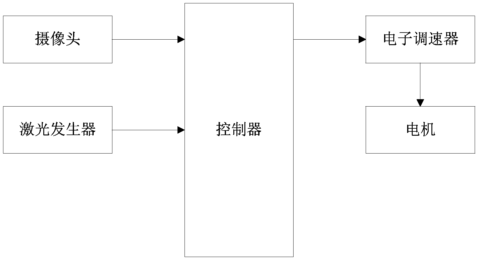
[0025] like figure 1 As shown, a rotorcraft automatic landing system includes a controller, a laser generator, a camera, an electronic governor and a motor for driving the rotor of the rotorcraft.

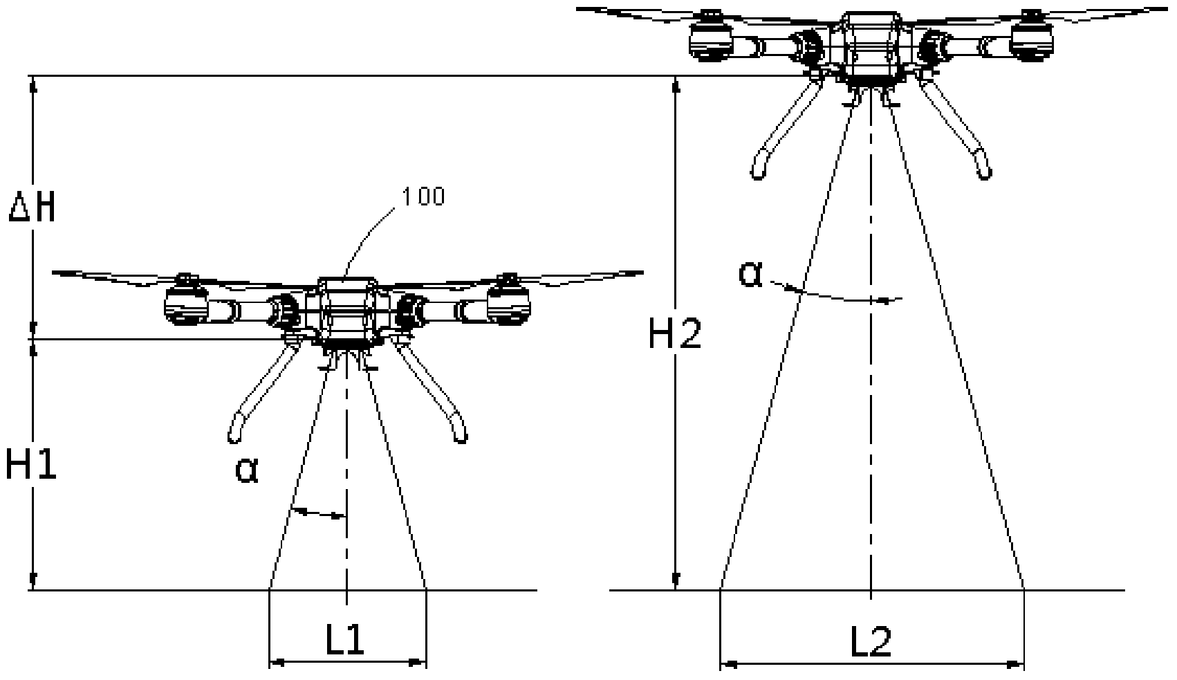
[0026] Both the laser generator and the camera are located at the bottom of the rotorcraft's fuselage. The laser generator has two emitting heads, and a laser beam emitted by the two emitting heads respectively forms an axisymmetric distribution with the central axis of the fuselage as the axis of symmetry, the central axis is perpendicular to the horizontal plane of the ground, and the laser beam and the central axis The angle α formed between them is an acute angle.

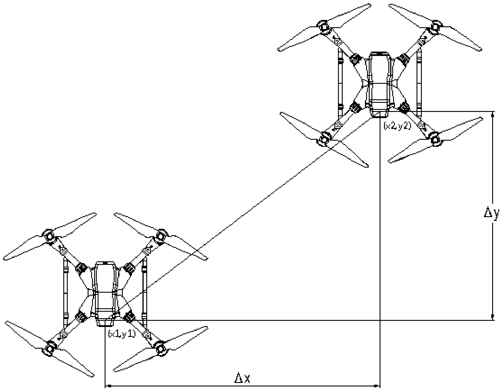
[0027] The camera is used to acquire the image of the landing target and the distance image formed by the projection of the two laser beams on the ground, that is, two points will b...


PUM


Abstract

The invention relates to an automatic landing system and method of a rotor aircraft. The system comprises a controller, a laser generator, a camera, an electronic speed regulator and a motor for driving a propeller of the rotor aircraft to rotate; the laser generator and the camera are located at the bottom of a fuselage of the rotor aircraft; the laser generator is provided with two emission heads; laser beams emitted by the two emission heads are axially symmetrically distributed by taking the central axis of the fuselage as the symmetrical axis; the central axis is vertical to the horizontal plane of the ground; and an included angle formed between the laser beams and the central axis is an acute angle. According to the automatic landing system and method of the rotor aircraft, the laser generator, the camera and the controller are matched, so that the flying speed and the displacement of the rotor aircraft can be controlled, and the automatic landing effect is realized.

Description


Claims


Application Information

Patent Timeline
Owner GUANGZHOU XAIRCRAFT TECH CO LTD
Why Eureka
Try Eureka