

Fuze isolation mechanism
A technology for isolating mechanisms and fuzes, applied in fuzes, weapon accessories, offensive equipment, etc., can solve problems such as poor recoverability and low safety factor, and achieve the effect of low cost, high safety, and state recovery
- Summary
- Abstract
- Description
- Claims
- Application Information
AI Technical Summary
Problems solved by technology
Method used
Image

Examples
specific Embodiment 1
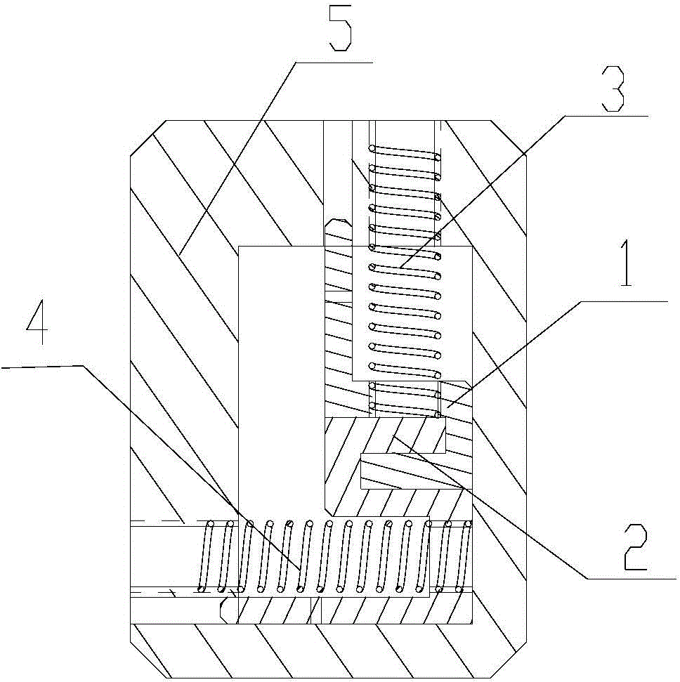
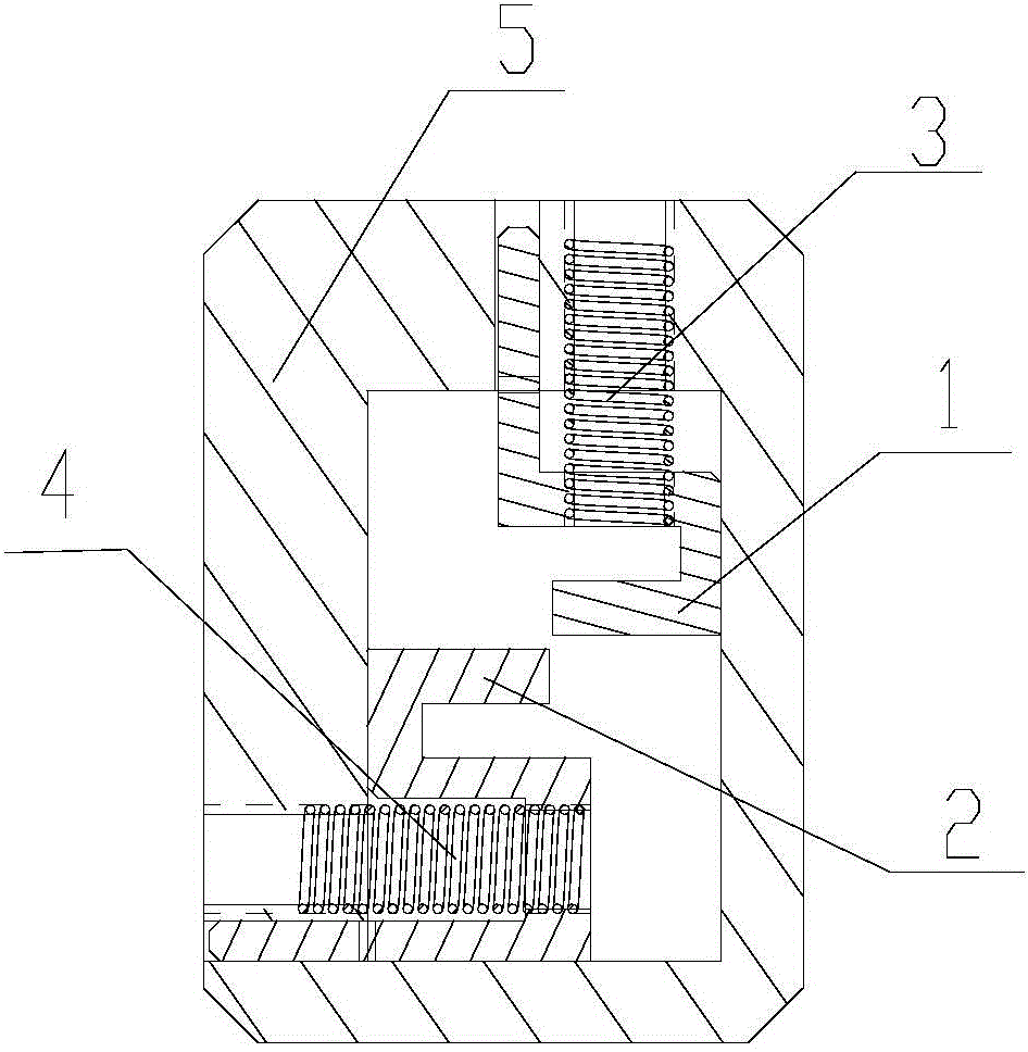
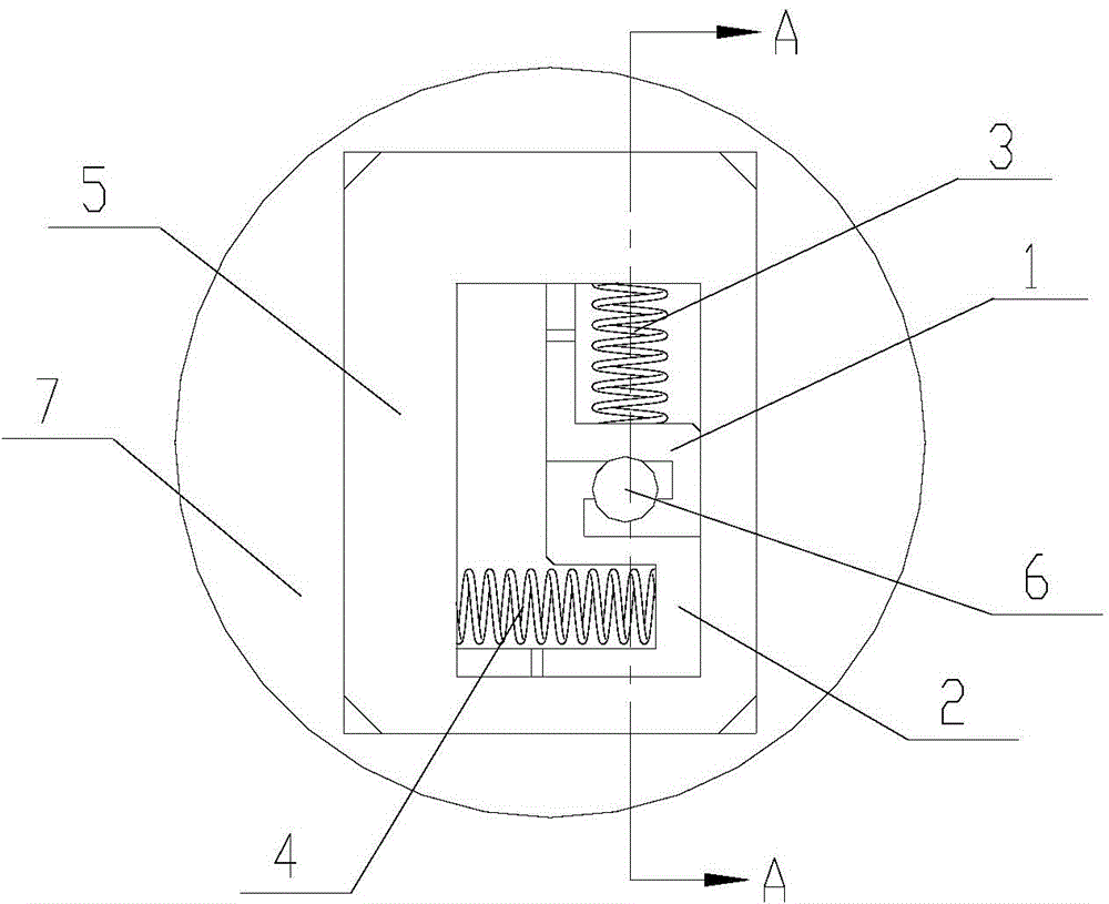
[0020] Such as figure 1 As shown, this example includes a first U-shaped partition 1 , a second U-shaped partition 2 , a first spring 3 , a second spring 4 and a frame 5 . The frame 5 is equipped with a first spring 3 , a first U-shaped partition 1 , a second U-shaped partition 2 and a second spring 4 .
[0021] Both the first spring 3 and the second spring 4 are made of high-temperature shortened two-way CuZnAl shape memory alloy material. The first spring 3 is placed vertically, and its upper and lower ends are respectively threaded and fixed in the corresponding threaded holes on the upper surface of the frame 5 and the first U-shaped partition 1; the second spring 4 is placed horizontally, and its left and right ends are threaded respectively. It is fixed in the corresponding threaded holes on the side of the frame 5 and the second U-shaped partition 2. When the first spring 3 and the second spring 4 are installed on the first U-shaped partition 1 and the second U-shaped...
specific Embodiment 2
[0028]In this embodiment, except that when the first spring 3 and the second spring 4 are installed on the first U-shaped partition 1 and the second U-shaped partition 2 respectively, the compression amount is 10%, and the first spring 3 and the installation direction of the second spring 4 are perpendicular to each other. And the positions corresponding to the first U-shaped partition 1 and the second U-shaped partition 2 on the frame 5 are respectively provided with longitudinal and transverse guide grooves, the first U-shaped partition 1 and the second U-shaped partition 2 All stretch into outside 3mm in the guide groove of frame 5. Other compositions and connections are the same as in Example 1.
PUM
 Abstract
Description
Claims
Application Information