Spiral-flow type drainage converging device for building

A swirl type and concentrator technology, which is applied in the field of construction drainage concentrators, can solve the problems of easy drying of floor drain water seals, difficult maintenance, easy blockage of pipes, etc., and achieve the effect of preventing ground water leakage

Active Publication Date: 2015-06-24
KUNMING QUNZHIYING TECH
View PDF5 Cites 7 Cited by
  • Summary
  • Abstract
  • Description
  • Claims
  • Application Information

AI Technical Summary

Problems solved by technology

[0002] At present, when floor drains are installed in bathrooms, kitchens, and balconies on the same floor of the building, floor drains must be lowered or partially lowered. Air, harmful gases, bugs, etc. are easy to run into the room and affect the living and hygienic environment

Method used


Image

  • Spiral-flow type drainage converging device for building
  • Spiral-flow type drainage converging device for building
  • Spiral-flow type drainage converging device for building

Examples


Embodiment 1

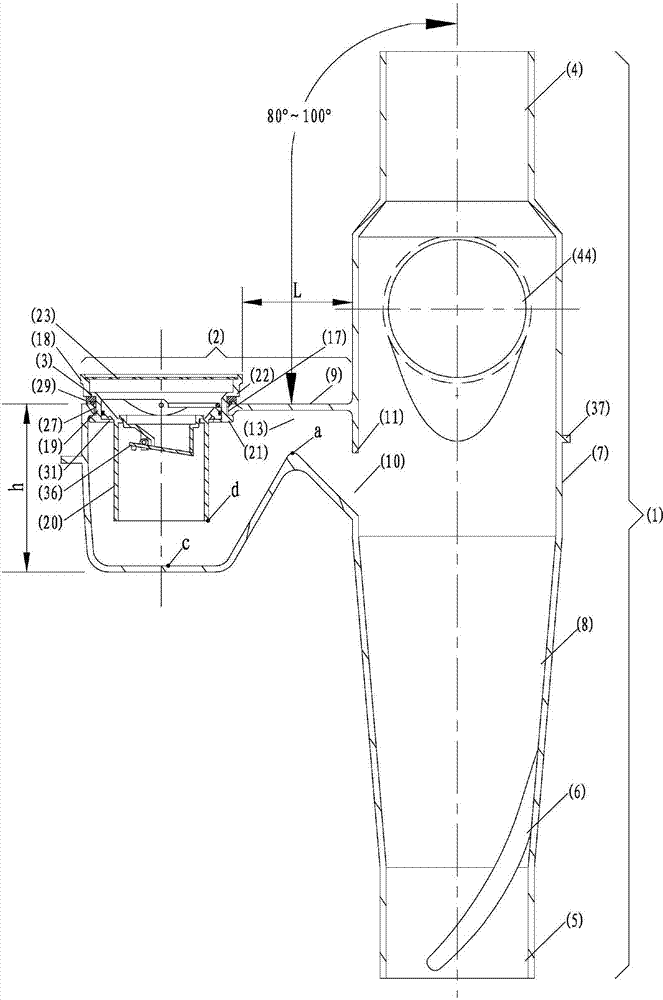
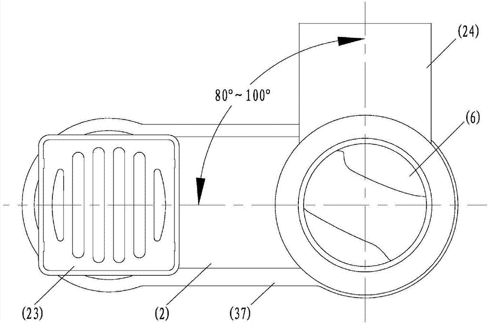
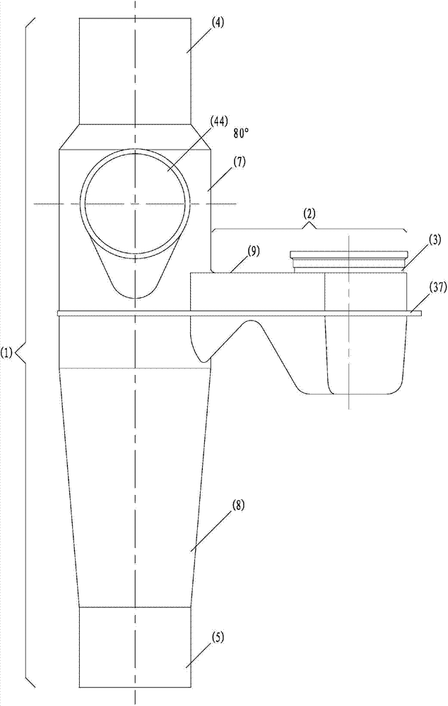
[0030] Such as figure 1 , 2 , 3, and 4, the architectural swirling drainage concentrator of the present invention is composed of a vertical pipe drainage section (1), a horizontal pipe drainage collection section (2) and a water seal member (3). The riser drainage section (1) is connected up and down, and the middle section has expansion, and there are guide vanes (6) in the expansion section. The expansion section is divided into straight section expansion (7) and funnel-shaped expansion (8), straight section expansion (7 ) There is a pipe section with the same outer diameter of 110mm in length at the expansion place, the straight section expansion (7) is located at the upper end of the funnel-shaped expansion (8), below the upper interface (4), and the funnel-shaped expansion (8) is at the lower interface (5) Above; the horizontal pipe drainage collection section (2) is located on one side of the vertical pipe drainage section (1), and the hollow part communicates with the ...

Embodiment 2

[0032] Such as Figure 5 , 6, 7, the inner diameter of the horizontal opening (17) of the building swirling drainage concentrator according to the present invention is circular or close to a circular opening (25), and there is a group (2) of symmetrical concave holes on the inner diameter circle. The notch (26), the arc length of a single notch mouth is 20mm, the depth is 4mm, and the diameter is 108mm. The outer diameter of the plug is 115mm, the inner diameter of the transverse opening (17) is 100mm, the outer diameter of the middle end (27) of the middle part (19) of the water seal member is 98mm; 21) is a group (2) of symmetrical bosses, the outer diameter of the boss (21) is 106mm, the arc length is 18mm, and the depth is 3mm, and the outer part of the middle part of the upper water seal member of the horizontal opening (17) (22) There is a sealing gasket (29) under the circular mouth plug. The inner diameter of the sealing gasket is 100mm and the outer diameter is 115m...

Embodiment 3

[0034] Such as Figure 10 , 11 As shown, the upper part (18) of the water seal member of the building swirling drainage concentrator according to the present invention and the lower part of the floor drain cover (23) have one or more interfaces (30°) at an angle of +2° with the horizontal direction. ), the interface (30) is used to connect drainage appliances in different directions, and the upper part (18) of the water seal member can also be rotated to rotate the direction of the interface (30) to facilitate the connection of drainage appliances in different directions. All the other are with embodiment 2.


PUM


Abstract

The invention relates to a drainage converging device for a bathroom, a balcony and a kitchen, in particular to a spiral-flow type drainage converging device for a building. The drainage converging device is composed of a vertical pipe drainage section (1), a transverse pipe drainage converging section (2) and a water seal component (3). A guide vane (6) is arranged in a dilatation section of the vertical pipe drainage section (1). A transverse section (9) and a lower inner wall of the transverse pipe drainage converging section (2) are planes or approximate to planes or arc surfaces. The maximum distance of a transverse opening (15) of a converging section top end channel (13) is larger than that of a vertical opening (16) of the converging section top end channel (13). The distance L between the inner wall edge of the hollow portion of a transverse surface opening (17) and the outer wall of the portion, close to the transverse surface opening, of the vertical pipe drainage section ranges from 40 mm to 450 mm. The water seal component (3) can be separated from the transverse surface opening (17). A floor drain cover (23) is arranged on the upper portion (18). The lowest end of a transverse pipe connector (44) is higher than the transverse surface (9). By the adoption of the spiral-flow type drainage converging device for the building, when drainage of the same floor of the building is conducted, under the condition that floor drains are arranged in the bathroom, the kitchen and the balcony, a floor descent plate and a slight descent plate are not needed.

Description

technical field [0001] The invention relates to a drainage collector for buildings, in particular to a drainage collector for toilets, balconies and kitchens. Background technique [0002] At present, when floor drains are installed in bathrooms, kitchens, and balconies on the same floor of the building, floor drains must be lowered or partially lowered. Gas, harmful gas, small insects, etc. are easy to run into the room and affect the living and hygienic environment. Contents of the invention [0003] The purpose of the present invention is to overcome the existing technical defects, to provide a kind of use toilet, kitchen, balcony in the same floor drainage in the building without any lowering floor or micro-lowering board, the pipeline below the drainage device is not easy to block, It is easy to overhaul, and the water seal of the floor drain is not easy to dry up, which can prevent odor, harmful gas, and small insects from entering the room, and can improve the livi...

Claims


Application Information

Patent Timeline
Patent Type & Authority Applications(China)
IPC IPC(8): E03F5/04E03C1/28E03F5/06
Inventor 林国强程宏伟邱寿华
Owner KUNMING QUNZHIYING TECH
Why Eureka
Try Eureka