3d printer platform calibration device

A 3D printer and platform calibration technology, applied in the direction of additive processing, etc., can solve the problems of occupying effective printing space, easy to fall off the clamping, single clamping effect, etc., achieve high practicability and promotion value, save effective working space, Reduce the effect of spare parts

Active Publication Date: 2017-01-25
JIANGSU HAOYU ELECTRONICS TECH
View PDF4 Cites 0 Cited by
  • Summary
  • Abstract
  • Description
  • Claims
  • Application Information

AI Technical Summary

Problems solved by technology

The problem is that when such a clip is in the clamping state, the two clamping arms form a certain angle, and the top surface of the work plate and the bottom surface of the work platform fixing frame are usually horizontal for fixing and clamping, so the clamping arms Compared with the two sides of the clamping, it will be relatively warped, the clamping is easy to fall off, unstable, and interferes with the normal operation of machines such as 3D printers
The traditional clips that play a clamping effect can only play a single clamping role. If calibration is required, an additional calibration device is required, which is cumbersome and takes up valuable effective printing space.

Method used


Image

  • 3d printer platform calibration device
  • 3d printer platform calibration device
  • 3d printer platform calibration device

Examples


Embodiment 1

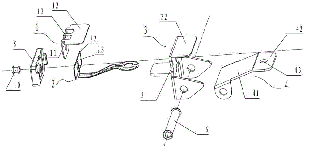
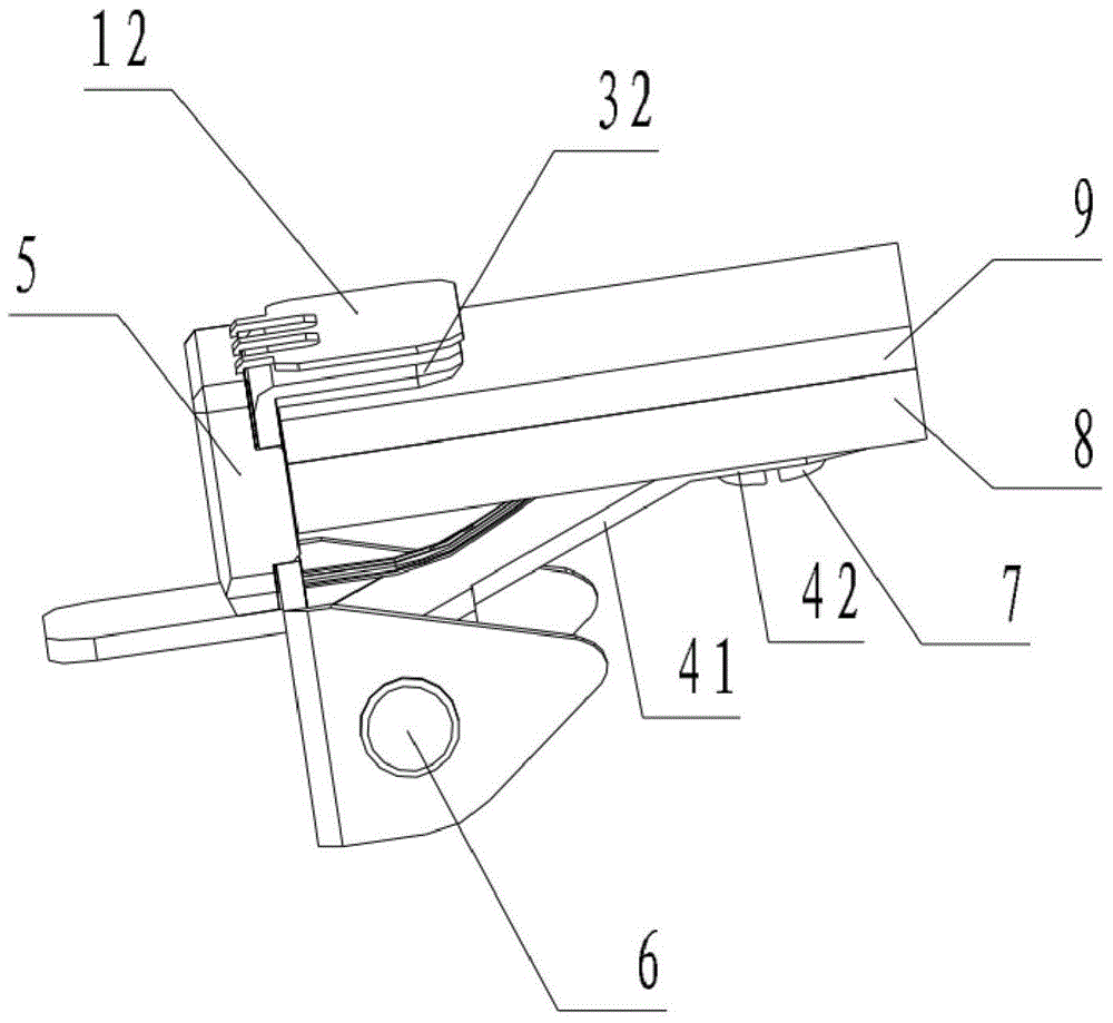
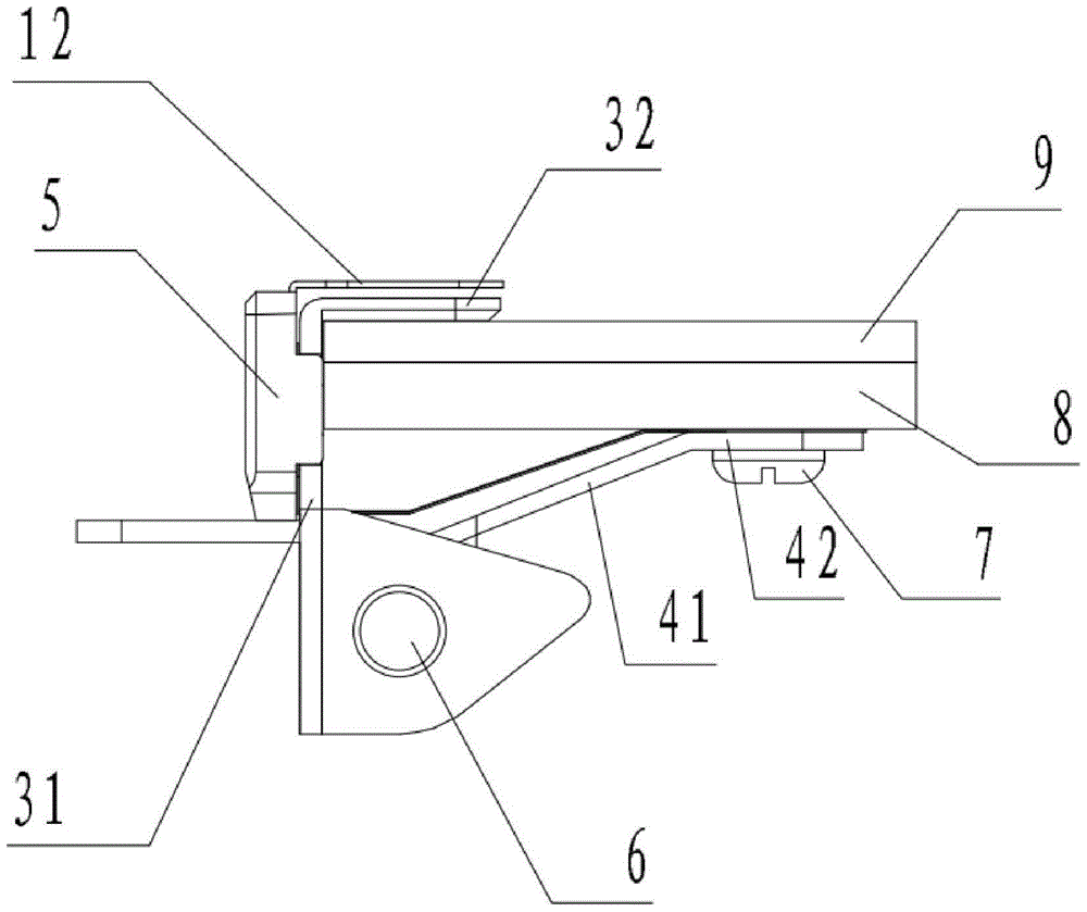
[0029] Embodiment 1: The 3D printer platform calibration device provided in this embodiment 1, the schematic three-dimensional view of its structure is as follows figure 2 As shown, the main view of the structure is as follows image 3 As shown, the left view of the structure is as follows Figure 4 shown, Figure 4 The A-A sectional view such as Figure 5 Shown, including a print head mounted on a 3D printer (not shown), a print platform and a platform alignment clip. The schematic assembly diagram of the structure of the platform calibration clip in Example 1 is as follows: figure 1 As shown, the platform calibration clip includes a conductive metal dome 1, a flexible circuit board 2 and a clip for holding the printing platform.

[0030] The printing platform includes a removable work plate 9 held together by several platform calibration clips and a work platform holder 8 inside the 3D printer, the top surface of the work plate 9 and the bottom surface of the clamping p...

Embodiment 2

[0041] Embodiment 2: The structure is basically the same as that of Embodiment 1, and the similarities are not repeated, but the differences are:

[0042] When the rivets or bolts pass through the perforations on the flexible circuit board 2 and the first body portion 31 of the conductive clamping body, they are insulated from the flexible circuit board 2 and the first body portion 31 of the conductive clamping body. Of course, it is also possible that the rivets or bolts are insulated from each passing component. For example, the rivets or bolts are plastic parts, or the rivets or bolts are metal parts, but the insulation treatment similar to Embodiment 1 is carried out when they pass through each part. In short, the rivets or bolts only need to be rivets or bolts that do not conduct the first conductive layer and the second conductive layer through which they penetrate.

[0043] In the second embodiment, the second contact portion 12 is a second contact portion arranged in ...


PUM


Abstract

The invention discloses a platform calibration device for a 3D printer. The platform calibration device comprises a 3D printing nozzle, a printing platform and platform calibrating clamps, wherein each platform calibrating clamp comprises a conductive metal elastic sheet, a flexible circuit board and a clamp for clamping; each clamp comprises a conductive clamping main body and an elastic clamping sheet, the conductive clamping main body comprises a first main body part and a first clamping part, the elastic clamping sheet comprises a second clamping part parallel to the first clamping part and an elastic extending sheet part which extends from the second clamping part and is relatively turnup; each flexible circuit board comprises a first conductive layer, an insulating layer and a second conductive layer; each conductive metal elastic sheet comprises a first contact part and a second contact part, the second contact part can be contacted with the corresponding first clamping part under the action of external force and can reserve a gap with the first clamping part without the action of the external force, the first contact part is parallel to and tightly attached to the corresponding first conductive layer, and the first main body part is parallel to and tightly attached to the corresponding second conductive layer. The platform calibration device for the 3D printer can conveniently realize a stable plane clamping function and an accurate platform calibration function required by the 3D printing work platform.

Description

technical field [0001] The invention relates to a platform calibration device, in particular to a platform calibration device on a 3D printer. Background technique [0002] The working platform (ie printing platform) of existing 3D printers, especially desktop 3D printers, is to use multiple commonly used clips to clamp the removable work plate and the work platform fixing frame inside the machine in different directions, so as to realize the work plate. fixed to form a printing work platform. The two clamping arms of the clamp are symmetrical, and the clamping effect is realized by opening and closing with the rotation center. The problem is that when such a clamp is in the clamping state, the two clamping arms form a certain angle, and the top surface of the work plate and the bottom surface of the work platform fixing frame are usually horizontal for fixing and clamping, so the clamping arm is usually horizontal. The two sides of the clamp will be relatively tilted, the...

Claims


Application Information

Patent Timeline
Patent Type & Authority Patents(China)
IPC IPC(8): B29C67/00B33Y30/00
Inventor 魏宏辉魏天浩魏妗羽
Owner JIANGSU HAOYU ELECTRONICS TECH
Why Eureka
Try Eureka