Electronic lock

An electronic lock head and lock head technology, applied in the field of locks, can solve the problems of complexity, high production cost, poor protection effect, etc.

Active Publication Date: 2015-08-26
ZHONGSHAN EFUD ELECTRONICS TECH
View PDF5 Cites 3 Cited by
  • Summary
  • Abstract
  • Description
  • Claims
  • Application Information

AI Technical Summary

Problems solved by technology

However, the internal structure design of the existing electronic lock head is complex and cumbersome, the structure and principle are traditional and old, not simple and reasonable enough, there are many parts, the production and processing are difficult, the consumption of raw materials is large, the production cost remains high, and the anti-theft function is weak. Poor protection effect, low stability and poor reliability

Method used


Image

  • Electronic lock
  • Electronic lock

Examples


Embodiment Construction

[0016] It should be understood that the specific embodiments described here are only used to explain the present invention, not to limit the present invention.

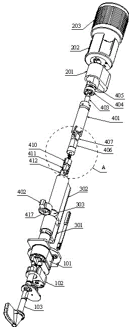
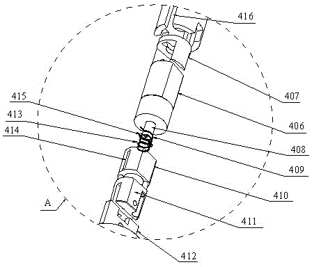
[0017] refer to Figure 1 to Figure 2 , an embodiment of an electronic lock head of the present invention is proposed, and the electronic lock head includes a front structure, a lock head part, and a rear end structure connected in sequence.

[0018] The front end structure includes a front lock head cover 101 arranged at the front end of the lock head part, a horn seat 102 and a knob 103 arranged at the front end of the front lock head cover 101 in turn.

[0019] The rear end structure includes a rear lock head cover 201 arranged at the rear end of the lock head part, and a circuit structure arranged at the rear end of the rear lock head cover 201 . The circuit structure includes a battery case 202 connected and fixed to the rear lock cover 201 , a circuit board arranged in the battery case 202 , and a battery conne...


PUM


Abstract

The invention discloses an electronic lock. The electronic lock comprises a front-end structure, a lock part and a rear-end structure provided with a circuit structure inside. The lock part comprises a lock shell and a lock cylinder structure. The lock shell is divided into a front-end part, a groove and a rear-end part. The lock cylinder structure comprises a motor base and a lock shifting fork, wherein the motor base is connected with the circuit structure through a linkage rod, and the lock shifting fork is embedded in the groove and arranged on the front end of the motor base in a sleeving mode. A motor assembly is embedded in the motor base and is provided with a transmission shaft forwards. The rotary shaft is sleeved with a torsion spring capable of rotating along with the rotary shaft and moving forwards and backwards. The torsion spring is sleeved with a rear push block and a front push block, the rear push block and the front push block can move along with the torsion spring, a clutch clamping piece capable of moving along with the front push block is fixedly clamped to the front end of the front push block, a first clamping groove is formed in the front end of the motor base, and a second clamping groove is formed in the lock shifting fork. The clutch clamping piece is clamped and inserted into the second groove from the rear end, can move forwards and backwards in the first clamping groove and in the second clamping groove along with the front push block, and accordingly idling or meshing linkage between the motor base and the lock shifting fork is achieved.

Description

technical field [0001] The invention relates to the technical field of locks, in particular to an electronic lock head. Background technique [0002] Locks are the main tool for people to prevent theft. One of the main means for thieves to commit crimes is to start with the locks, or destroy the locks by prying, smashing, twisting, dialing, drilling, etc., or use the master key to prepare the key technology to open the lock. The defensive performance of the lockset should be absolutely reliable, so that it can be opened without any technical means except the corresponding key. At present, the existing locks on the market generally include mechanical locks and electronic locks. The use of electronic locks is becoming more and more common, and has been widely used in hotels, commercial offices, residential areas and other fields. However, the internal structure design of the existing electronic lock head is complex and cumbersome, the structure and principle are traditional a...

Claims


Application Information

Patent Timeline
Patent Type & Authority Applications(China)
IPC IPC(8): E05B15/00E05B15/10
Inventor 饶秀琴
Owner ZHONGSHAN EFUD ELECTRONICS TECH
Why Eureka
Try Eureka