link

A technology of connectors and components, applied in fasteners, clothing, applications, etc., can solve problems such as socket damage, component cost increase, and difficult elastic deformation of legs

Active Publication Date: 2017-10-13
YKK CORP
View PDF6 Cites 0 Cited by
  • Summary
  • Abstract
  • Description
  • Claims
  • Application Information

AI Technical Summary

Problems solved by technology

Therefore, when setting the pull-out force when the engagement is released as a relatively strong force to a certain extent, it is necessary to set the inclination angle of the abutment surface of the engaging part and the engaged part at the contact position to be the same as the pull-out force. The pulling direction is close to a right angle. In the case of this structure, the elastic deformation of the leg is difficult to proceed smoothly, and the engaging part of the leg and the engaged part of the socket may be damaged when the engagement is released. can no longer be used
[0011] In addition, in the coupling disclosed in Patent Document 2, when the coupling is partially broken, the coupling cannot be used again, and when the coupling is configured to be disengaged by a force greater than a predetermined value , there is the same problem as the above-mentioned patent document 1
Moreover, for the structure that can release the holding of the connecting part by receiving a force of more than a predetermined value, a holding structure and a holding release mechanism are required. In order to release the holding with a force of a predetermined value, a complicated and high-precision mechanism is required on a small member, resulting in the failure of the member. cost increase

Method used


Image

  • link
  • link
  • link

Examples


Embodiment Construction

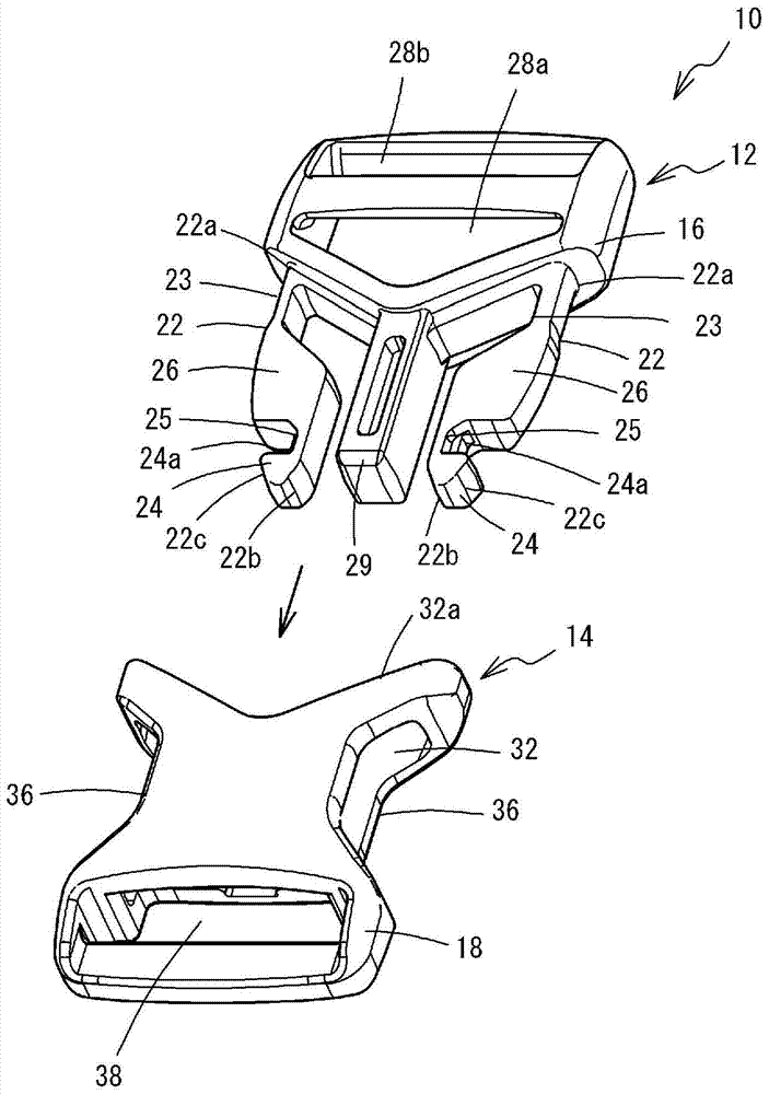
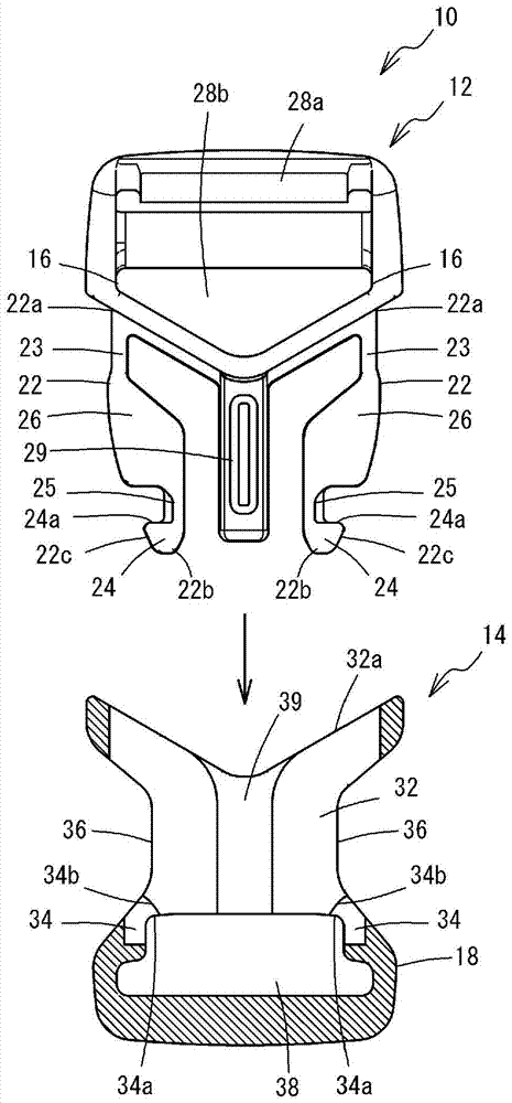
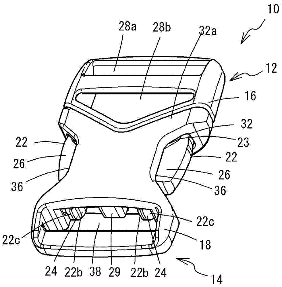
[0042] Below, according to Figure 1 to Figure 7 The buckle 10 which is the first embodiment of the coupling tool of the present invention will be described. The buckle 10 of the present embodiment includes a plug 12 and a socket 14 which are attached to a belt of a bag or the like not shown, a cord body, and an end of other members. The plug 12 and the socket 14 are each integrally formed of synthetic resin such as polyoxymethylene, polyamide, polypropylene, etc., and the plug 12 is inserted into the socket 14 to be connected to the socket 14 .

[0043]The plug 12 is provided with a pair of leg portions 22 that protrude in parallel from both sides of the base portion 16 of the plug 12 and are formed symmetrically with each other. At the base end portion 22 a of each leg portion 22 , a thin-walled first elastic deformation portion 23 that is relatively easily elastically deformed is formed such that a part of the outer surface of the leg portion 22 is recessed. Engaging port...


PUM


Abstract

The present invention is a connecting piece comprising a plug (12) and a socket (14), the plug (12) and the socket (14) are set to be able to connect and disconnect each other, and each has a mounting part for mounting to other components ( 28a, 38). The connector has a protruding portion (22) protruding from a base portion (16) of the plug (12) and an engaging portion (24) formed on the protruding portion (22). The socket (14) has a housing portion (32) for housing the protruding portion (22), and an engaged portion (34) formed on the housing portion (32) to engage the engaging portion (24). The plug (12) or socket (14) has an operation piece (26) for disengaging the engagement between the engaging portion (24) and the engaged portion (34). A first elastic deformation part (23) and a second elastic deformation part (25) are provided on the protruding part (22). Elastic deformation, the second elastic deformation part (25) is formed at a position different from that of the first elastic deformation part (23), when the plug (12) is connected to the socket (14), when the plug (12 ) and the socket (14) are separated from each other by a load, the second elastic deformation portion (25) can release the engagement between the engaging portion (24) and the engaged portion (34) under a load above a specified value. Elastic deformation in the way of engagement.

Description

technical field [0001] The present invention relates to a fastener such as a buckle that includes a male member and a female member and is capable of being connected to and released from each other. Background technique [0002] Conventionally, a buckle has been used as a coupling tool for detachably coupling two coupling objects such as ends of string-like members. The buckle includes a plug as a male member and a receptacle as a female member into which the plug is inserted and engaged. The plug includes a plug body and a pair of legs formed at both sides of the plug body parallel to each other. An operation piece and an engaging portion are respectively formed at the tip portion of each leg. The socket includes a socket body and an insertion hole formed in the socket body and into which a plug is inserted. In the insertion hole, there is formed an abutting portion that abuts against the legs and elastically displaces each leg inward, and an engaged portion for engaging...

Claims


Application Information

Patent Timeline
Patent Type & Authority Patents(China)
IPC IPC(8): A44B11/25
CPCA44B11/266
Inventor 高樱亮一郎
Owner YKK CORP
Why Eureka
Try Eureka