

Path distribution method and device thereof
A path allocation and path technology, applied in digital transmission systems, electrical components, transmission systems, etc., can solve the problems of low transmission rate and long transmission delay, and achieve faster transmission rate, scientific and reasonable path allocation, and save path allocation time. Effect
- Summary
- Abstract
- Description
- Claims
- Application Information
AI Technical Summary
Problems solved by technology
Method used
Image

Examples
Embodiment 1
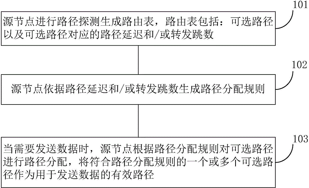
[0066] refer to figure 1 , which shows a flow chart of a path assignment method according to an embodiment of the present invention. This embodiment may specifically include the following steps:
[0067] Step 101, the source node performs path detection to generate a routing table, the routing table includes: optional paths and path delays and / or forwarding hops corresponding to the optional paths.
[0068] It should be noted that the optional path is the path through which the data travels from the source node to the target node. When the target node is a direct node of the source node, the optional path is directly from the source node to the target node; when the target node is not the source node When the node is a direct node, the data needs to go through multiple detected nodes from the source node to the target node. The path delay corresponding to the optional path refers to the time it takes for data to reach the target node from the source node, and then return from...
Embodiment 2
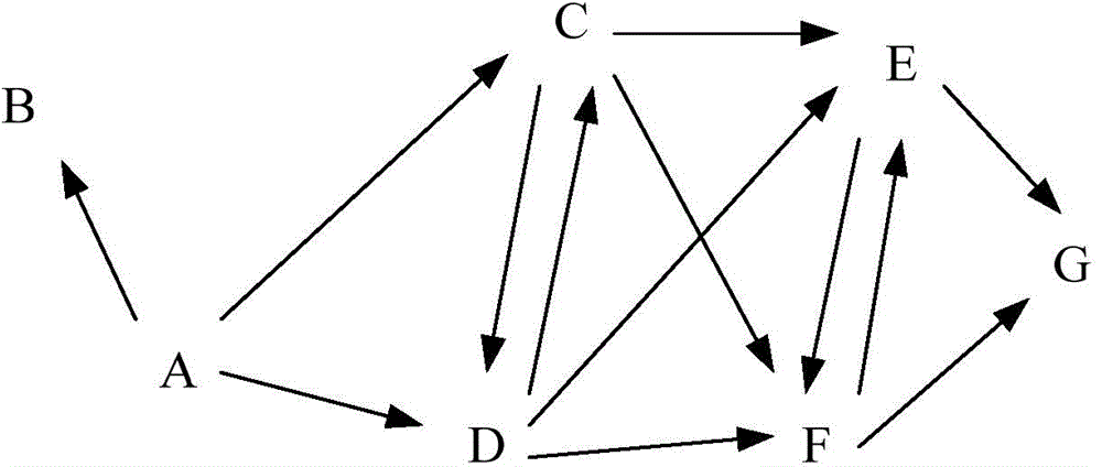
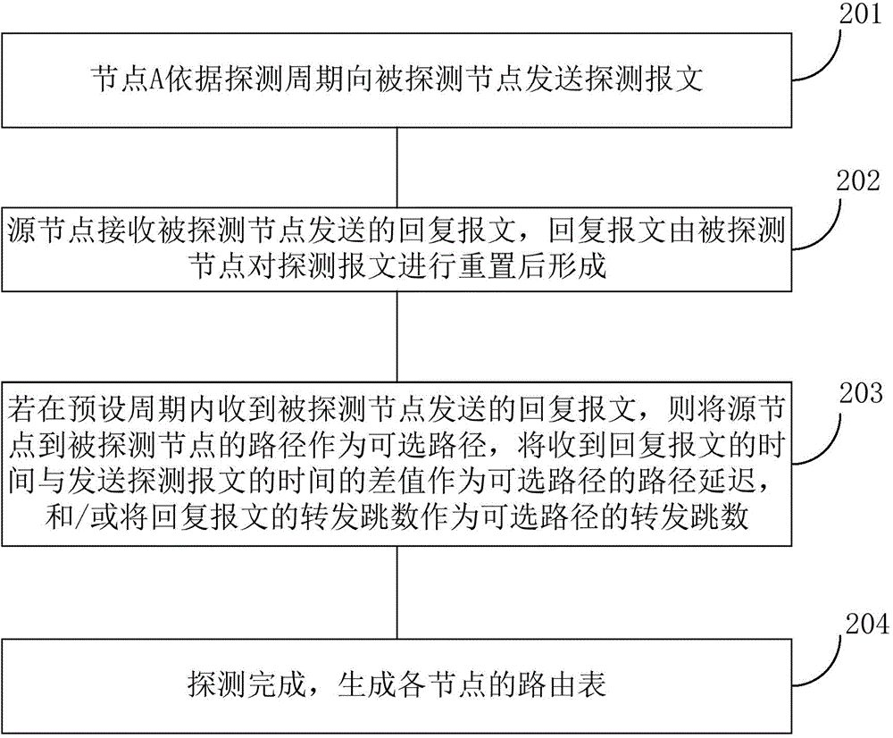
[0080] In a preferred embodiment of the present invention, figure 1 In step 101 of the embodiment, the source node performs path detection to generate a routing table, which may specifically include: the source node sends a detection message to the detected node according to the detection cycle, and the source node receives a reply message sent by the detected node, and the reply message is composed of Formed after the detected node resets the detection message; if the reply message sent by the detected node is received within the preset period, the path from the source node to the detected node is taken as an optional path, and the received The difference between the time of the reply message and the time of sending the probe message is used as the path delay of the optional path, and / or the forwarding hop count of the reply message is used as the forwarding hop count of the optional path. Combine below figure 2 The schematic diagram of the nodes shown and image 3 The flo...
Embodiment 3
[0114] In a preferred embodiment of the present invention, figure 1 In step 102 of the embodiment, the source node generates a path allocation rule according to the path delay and / or forwarding hop count, which may specifically include: the source node sorts the optional paths in the routing table according to the order of path delay from small to large; The minimum path delay is used as the delay base; the multiple of the delay base is set as the delay threshold; sequentially determine whether the sorted optional paths reach the delay threshold; if the path delay does not reach the delay threshold, set The optional path corresponding to the path delay is used as an effective path; and / or, the source node sorts the optional paths in the routing table in ascending order of forwarding hops; the smallest forwarding hop is used as the forwarding base; The multiple of the forwarding base is set as the forwarding threshold; sequentially determine whether the sorted optional paths re...
PUM
 Abstract
Description
Claims
Application Information