Stable connecting structure for drawer and slide rail of furniture
What is Al technical title?
Al technical title is built by PatSnap Al team. It summarizes the technical point description of the patent document.
A technology for connecting structures and furniture, which is applied to drawers, furniture parts, household appliances, etc. It can solve the problems of not meeting user requirements, unstable assembly relationship, and affecting the exquisiteness of drawers, so as to improve user experience, beautiful appearance, and Neat and exquisite effect
Active Publication Date: 2015-11-18
伍志勇
View PDF5 Cites 5 Cited by
Summary
Abstract
Description
Claims
Application Information
AI Technical Summary
This helps you quickly interpret patents by identifying the three key elements:
Problems solved by technology
Method used
Benefits of technology
Problems solved by technology
It is said that the structure is detachably connected between the side plate and the moving slide rail through a detachable locking mechanism, which makes the disassembly and assembly of the two fast and convenient; There are many gaps, which affect the exquisiteness of the drawer, and the assembly relationship between the components is unstable. It is easy to cause damage due to human reasons during use, transportation or packaging, which affects the service life and leads to waste of materials, thereby improving manufacturing. The cost can neither meet the requirements of users, nor can manufacturers and sellers get higher profits from it.
Method used
Image
Click on the blue label to locate the original text in one second.
Reading with bidirectional positioning of images and text.
Examples
Embodiment Construction
[0023] The present invention will be further described below in conjunction with the accompanying drawings and embodiments.
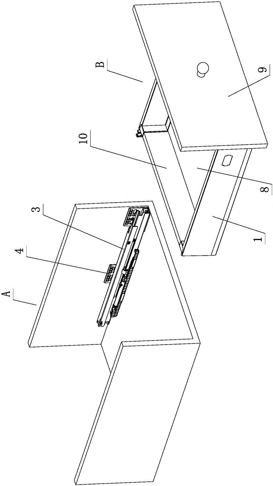
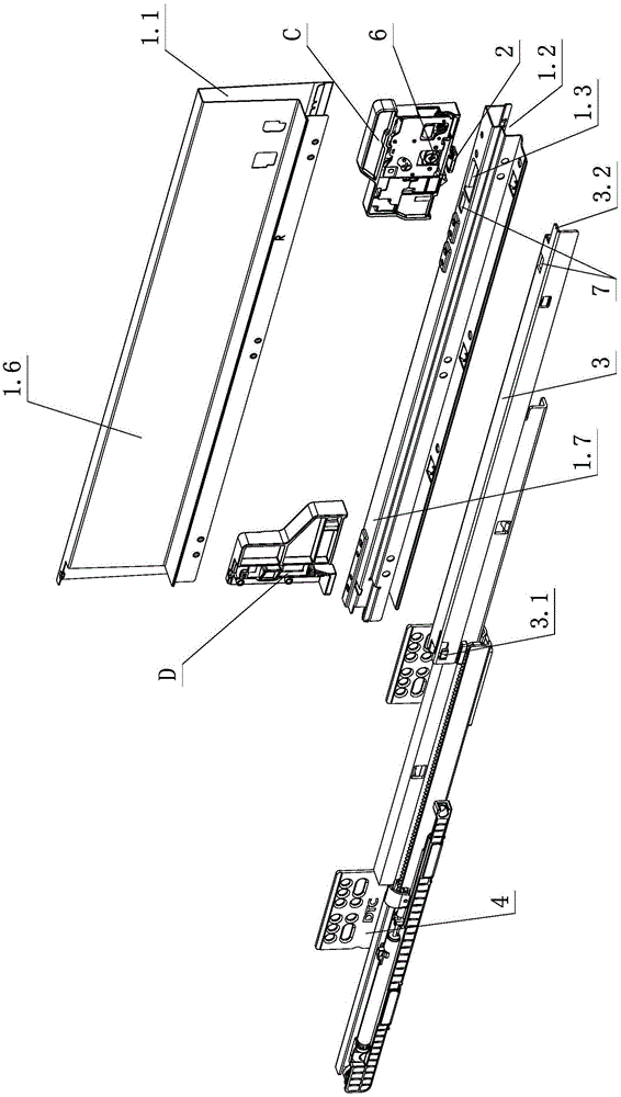
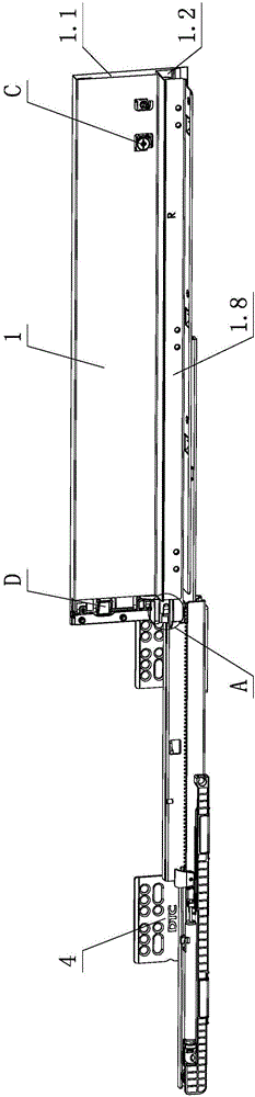
[0024] see Figure 1-Figure 8 , the stable connection structure between the furniture drawer and the slide rail, including the furniture cabinet body A, the slide rail assembly, and the furniture drawer B slidingly opened and closed on the furniture cabinet body A through the slide rail assembly; wherein, the furniture drawer B at least includes side panels 1. The upper part of the side plate 1 is provided with a cavity 1.1, and the lower part is provided with an assembly groove 1.2. The cavity 1.1 is provided with a front connecting device C, and the front connecting device C is provided with a connecting part 2. The connecting part 2 is at least partly assembled during assembly. Placed on the assembly groove 1.2, the slide rail assembly includes at least a moving slide rail 3 and a fixed slide rail 4 that slide and cooperate with each other. The rear ...
PUM
Abstract
A stable connecting structure for a drawer and a slide rail of a piece of furniture comprises a furniture cabinet body, a slide rail assembly and a furniture drawer, wherein the upper portion of the side plate of the furniture drawer is provided with a cavity, the lower portion of the side plate of the furniture drawer is provided with an assembly groove, a front connecting device is arranged on the cavity, a connecting portion is arranged on the front connecting device, the inner top face of the assembly groove extends to form a supporting portion, a movable slide rail of the slide rail assembly is arranged on the side plate, the rear end of the movable slide rail is connected to the rear end of the side plate through a buckling-hooking portion in a clamped mode when the movable slide rail and the side plate are assembled, the front end of the movable slide rail is clamped to the connecting portion of the front connecting device through a connecting-matching portion in a clamped mode, and when the side plate is stressed with respect to the movable slide rail at least in the upper direction and the lower direction, the connecting portion and the supporting play a mutual supporting role to enhance the connecting stability between the side plate and the movable slide rail. By the adoption of structural improvement, the stable connecting structure for the drawer and the slide rail of the furniture has the advantages that the stable connecting structure is simple, reasonable, excellent in performance, safe, reliable, low in manufacturing cost, convenient and fast to assemble, the members are compact, stable and firm in connection, the service life is long, the appearance is attractive and the like, and is good in practicability.
Description
technical field [0001] The invention relates to a stable connection structure, in particular to a stable connection structure between a furniture drawer and a slide rail. Background technique [0002] Chinese Patent Document No. CN203137617U disclosed on August 21, 2013 a detachable locking mechanism for drawer slide rails and side panels. It is provided with a front connector for connecting the front panel and a rear connector for connecting the back panel. The side plate is provided with a slot for accommodating the bottom plate. The bottom plate is set in the slot and acts on the moving slide rail of the slide rail assembly. ; There is a detachable locking mechanism between the side plate and the moving slide rail, and the moving slide rail is detachably connected with the side plate through the locking mechanism. It is said that the structure is detachably connected between the side plate and the moving slide rail through a detachable locking mechanism, which makes the ...
Claims
Application Information
Patent Timeline
Application Date:The date an application was filed.
Publication Date:The date a patent or application was officially published.
First Publication Date:The earliest publication date of a patent with the same application number.
Issue Date:Publication date of the patent grant document.
PCT Entry Date:The Entry date of PCT National Phase.
Estimated Expiry Date:The statutory expiry date of a patent right according to the Patent Law, and it is the longest term of protection that the patent right can achieve without the termination of the patent right due to other reasons(Term extension factor has been taken into account ).
Invalid Date:Actual expiry date is based on effective date or publication date of legal transaction data of invalid patent.