AI technical title is built by PatSnap AI team. It summarizes the technical point description of the patent document.
A drying machine and drying warehouse technology, applied in the fields of food science, food preservation, application, etc., can solve the problems affecting the smooth progress of the drying process, and achieve the effect of overcoming the technical bottleneck
Active Publication Date: 2019-12-24
SUZHOU KAILING FOOD CO LTD
View PDF11 Cites 0 Cited by
Summary
Abstract
Description
Claims
Application Information
AI Technical Summary
This helps you quickly interpret patents by identifying the three key elements:
Problems solved by technology
Method used
Benefits of technology
Problems solved by technology
[0008] In order to overcome the above problems, the present invention provides a continuous microwave vacuum ice-temperature dryer and its working method for industrial production, which overcomes the limitations of the above-mentioned ice-temperature dryer, and solves the problem of industrial microwaves being used in large-scale vacuum drying equipment due to vacuum Bottleneck problems affecting the smooth progress of the drying process due to discharge and electric field breakdown
Method used
Image
Click on the blue label to locate the original text in one second.
Reading with bidirectional positioning of images and text.
Examples
Embodiment 1
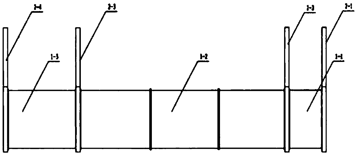
[0053] In Example 1, the vacuum precooling and drying chamber 1-1, the far-infrared drying chamber 1-2 and the microwave drying chamber 1-3 are respectively equipped with a vacuum system, a heating system, a condensation system and a loading system.
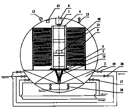
[0054] (1) Open the first isolating valve 2-1, put the feed truck containing the material to be dried into the vacuum pre-cooling and drying chamber 1-1, the roller 6 enters the guide rail 5, the nylon rack 7 meshes with the feed truck drive gear 8, and the material The feed tray on the car is just inserted between the far-infrared radiation plates 10.
[0055] (2) Start the command switch trigger, close the first isolation valve 2-1, the command switch is triggered, and the control system of the vacuum precooling and drying chamber 1-1 enters the following procedure:
[0056] a Open the condensing coil control valve 17 to keep the temperature of the cold trap at about -15°C;
[0057]b Open the control valve 20 of the vacuum pip...
Embodiment 2
[0092] Embodiment 2: the vacuum pre-cooling drying bin 1-1 is provided with a vacuum system, a loading system and a condensation system, and the far-infrared drying bin 1-2 and the microwave drying bin 1-3 are respectively provided with a vacuum system, a loading In addition to the material system and the condensation system, there are also heating systems.
[0093] (1) Open the first isolation valve 2-1, push the material trolley with the material to be dried into the vacuum precooling and drying chamber 1-1, the roller 6 enters the guide rail 5, and the nylon rack 7 meshes with the gear 8 of the trolley driving device.
[0094] (2) Start the command switch trigger, close the first isolation valve 2-1, the command switch is triggered, and the control system of the vacuum precooling and drying chamber 1-1 enters the following procedure:
[0095] a Open the condensing coil control valve 17 to keep the temperature of the cold trap at about -15°C;
[0096] b Open the control val...
PUM
Abstract
A drying machine comprises a cavity, a vacuum system, a heating system, a condensation system, a material carrying system and a control system, wherein the vacuum system, the heating system, the condensation system, the material carrying system and the control system are arranged in the cavity, and the control system controls operation of the vacuum system, the heating system, the condensation system and the material carrying system. The cavity comprises a vacuum pre-cooling drying bin, a far infrared drying bin and a microwave drying bin. The cavity is provided with a first isolation valve, a second isolation valve, a third isolation valve and a fourth isolation valve. The front end of the vacuum pre-cooling drying bin is connected with the outside of the bin through the first isolation valve, and the rear end of the vacuum pre-cooling drying bin is connected with the far infrared drying bin through the second isolation valve. The front end of the far infrared drying bin is connected with the vacuum pre-cooling drying bin through the second isolation valve, and the rear end of the far infrared drying bin is connected with the microwave drying bin through the third isolation valve. The front end of the microwave drying bin is connected with the far infrared drying bin through the third isolation valve, and the rear end of the microwave drying bin is connected with the outside of the bin through the fourth isolation valve. The control system controls opening and closing of the first isolation valve, the second isolation valve, the third isolation valve and the fourth isolation valve.
Description
technical field [0001] The invention relates to a drying machine, in particular to a continuous microwave vacuum ice-temperature drying machine. Background technique [0002] Ice temperature drying technology is a new food drying method born from the application of ice temperature storage theory to the field of food drying. In the traditional low-temperature storage of food, storage above 0°C and below 10°C is called refrigeration, and below 0°C is called freezing. The freezing point of food, also known as the freezing point, is lower than 0°C. When the temperature is lower than 0°C and higher than the freezing point, the food cells are always in a living state. The inventor of ice temperature technology, Dr. Yamane Akimi from Japan, defines the area below 0°C and above the freezing point as the "ice temperature zone" of the food. Preserving food in this temperature zone can not only effectively reduce the energy consumption of refrigeration equipment, but also Overcome th...
Claims
Application Information
Patent Timeline
Application Date:The date an application was filed.
Publication Date:The date a patent or application was officially published.
First Publication Date:The earliest publication date of a patent with the same application number.
Issue Date:Publication date of the patent grant document.
PCT Entry Date:The Entry date of PCT National Phase.
Estimated Expiry Date:The statutory expiry date of a patent right according to the Patent Law, and it is the longest term of protection that the patent right can achieve without the termination of the patent right due to other reasons(Term extension factor has been taken into account ).
Invalid Date:Actual expiry date is based on effective date or publication date of legal transaction data of invalid patent.

