Power-losing trigger type steel wire rope brake and braking method thereof

A wire rope and brake technology is applied in the field of power failure trigger wire rope brake and its braking, which can solve the problem of lack of safety protection devices in the elevator car, achieve reliable and fast clamping and braking, realize the protection effect, and realize the safety control. moving effect

Active Publication Date: 2016-04-13
SHIJIAZHUANG WULON BRAKE
View PDF11 Cites 16 Cited by
  • Summary
  • Abstract
  • Description
  • Claims
  • Application Information

AI Technical Summary

Problems solved by technology

[0008] The purpose of the present invention is to provide a power-off trigger type wire rope brake and its braking method to solve the problem of lack of a practical safety protection device for the unexpected movement of the elevator car

Method used


Image

  • Power-losing trigger type steel wire rope brake and braking method thereof
  • Power-losing trigger type steel wire rope brake and braking method thereof
  • Power-losing trigger type steel wire rope brake and braking method thereof

Examples


Embodiment 1

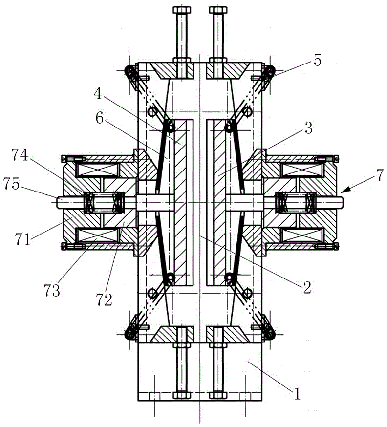
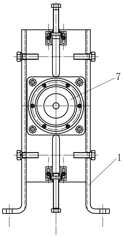
[0049] like figure 1 , figure 2 , image 3 As shown, the frame 1 is a three-dimensional frame structure in the shape of a square column, and upper and lower opposite slit openings are arranged on the top surface and the bottom surface of the frame 1, and two brake clips with opposite clamping surfaces are arranged in the frame 1, A rope channel 2 is formed between the clamping surfaces of the two brake clips, and the rope channel 2 is vertically opposite to the slit-shaped opening on the frame 1 , so that the traction wire rope 10 can pass up and down in the frame 1 . The two brake clips are arranged opposite to each other, and the opposite surfaces of the brake clips are clamping surfaces parallel to each other, and a friction plate 3 is arranged on the clamping surface of each brake clip. The two brake clips in this embodiment are both movable clips 4 , and the two movable clips 4 have the same structure and are arranged symmetrically in the frame 1 .

[0050] figure 1 ...

Embodiment 2

[0061]The structure of this embodiment is basically the same as that of Embodiment 1, and it is also the setting structure of double movable clamping blocks, and is provided with two brake trigger mechanisms; the front ends of the brake push rods 75 in the two brake trigger mechanisms respectively push Trigger braking is performed in the chute 6 of the movable clamp block 4 on each side.

[0062] The difference is that the rope channel 2 is an upper and lower channel that is surrounded by three sides and opened on one side by the frame 1, the brake clip and the end plate 8 ( Figure 5 ). The open structure of the side of the rope passage is convenient for installing the brake of the present invention on the elevator equipment that is not easy to disassemble, that is, the steel wire rope 10 on the elevator can enter the rope passage 2 through the open side, thereby greatly facilitating the installation of the rope gripper.

Embodiment 3

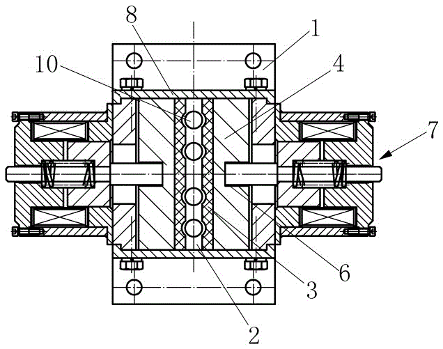
[0064] like Image 6 As shown, the structure of this embodiment is basically the same as that of Embodiment 1, except that one of the two brake clips in the frame 1 is a movable clip 4, and the other is a fixed clip 9; the fixed clip 9 is fixed on the frame 1, and save the setting of a corresponding brake trigger mechanism. Therefore, in this embodiment, only the frame 1 on one side of the movable clamp block 4 is provided with a brake trigger mechanism, and the brake trigger mechanism includes a brake electromagnet 7, a compression spring 74, a brake push rod 75, and the like. Similarly, the braking electromagnet 7 is composed of a yoke 71, an armature 72 and an electromagnetic coil 73; the compression spring 74 is installed in the inner cavity of the braking electromagnet 7 (it can also be arranged outside the braking electromagnet) , the brake push rod 75 passes through the yoke 71 , the armature 72 and the compression spring 74 , and maintains a linkage structure with the...


PUM


Abstract

The invention relates to a power-losing trigger type steel wire rope brake and a braking method thereof. According to the structure of the steel wire rope brake, a rope channel is arranged in a frame; braking clamp blocks are arranged on the two sides of the rope channel respectively; friction plates are arranged on clamping faces of the two braking clamp blocks respectively; at least one of the two braking clamp blocks is a movable clamp block; tension springs are arranged on the frame, so that the back faces of the movable clamp blocks are attached to the inner edge of the frame; longitudinal sliding grooves are formed in the back faces of the clamping faces of the movable clamp blocks; power-losing trigger braking electromagnets are arranged on the frame and provided with braking push rods abutting against the interiors of the sliding grooves in the back faces of the movable clamp blocks; and E-shaped faces with the middles protruding are arranged on the back faces of the movable clamp blocks, and a conical face with the middle concaved is arranged on the inner edge of the frame. An elevator car or a weight can be immediately clamped by the steel wire rope brake during upward heading and downward sliding, and malignant consequences caused by accidents are avoided.

Description

technical field [0001] The invention relates to a safety brake, in particular to a power failure trigger type wire rope brake and a braking method thereof. Background technique [0002] In recent years, accidents of elevators slipping, rushing to the top, and squatting at the bottom have occurred from time to time. In order to curb the occurrence of such accidents, elevators have been added to the No. Mandatory requirements for safety protection devices to prevent accidental movement of the car should be added to prevent vicious casualties caused by accidental movement of the car. [0003] The existing safety protection devices to prevent the accidental movement of the car are divided into the following three methods: [0004] The first way is to add a separate set of brakes on the basis of the original brakes as a redundant design. The disadvantage of this form is that if the car unexpectedly moves in the power failure state, the two brakes will act at the same time, whic...

Claims


Application Information

Patent Timeline
Patent Type & Authority Applications(China)
IPC IPC(8): B66B5/24
CPCB66B5/24
Inventor 韩伍林郝雄毅
Owner SHIJIAZHUANG WULON BRAKE
Why Eureka
Try Eureka