Floor drain display device

A technology for display devices and floor drains, applied in water supply devices, indoor sanitary plumbing devices, waterway systems, etc., to achieve rapid opening and closing, simple structure, and low fluid resistance

Inactive Publication Date: 2016-05-04
ZHEJIANG INT MARITIME COLLEGE
View PDF5 Cites 5 Cited by
  • Summary
  • Abstract
  • Description
  • Claims
  • Application Information

AI Technical Summary

Problems solved by technology

Therefore, after the floor drain is produced, some tests will be carried out. In the existing commercial activities, there is a lack of display devices to demonstrate the performance of the floor drain.

Method used


Image

  • Floor drain display device
  • Floor drain display device

Examples


no. 1 example

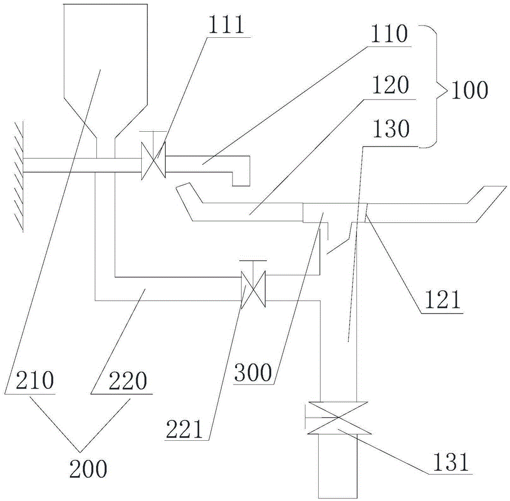
[0032] Reference attached figure 1 , a floor drain display device provided in the first embodiment of the present invention, comprising a drain display part 100 and an anti-water back display part 200 .

[0033] The sewer display part 100 includes a water inlet pipe 110, a water tank 120, and a water drain pipe 130. Water, open the water inlet valve 111, the water in the water inlet pipe 110 flows down from the mouth of the pipe, and flows into the water tank 120. The bottom of the water tank 120 is provided with a water outlet 121 for installing the floor drain 300. The water pipe 130 communicates with the water outlet 121, and the floor drain 300 It is sealed and installed with the water outlet 121 , that is, the water in the water tank 120 can only enter the water pipe 130 through the floor drain 300 , and the bottom end of the water pipe 130 is provided with a water shut-off valve 131 . When displaying the water, the water stop valve 131 is opened first, and then the wate...

no. 2 example

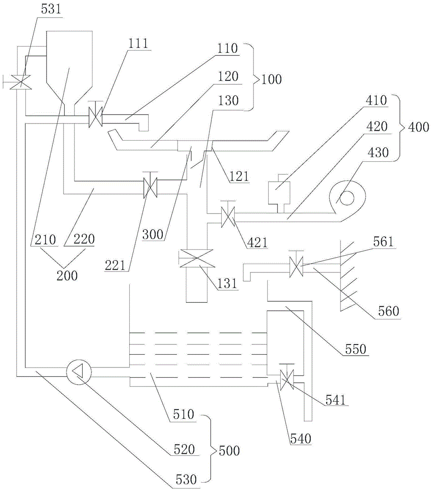
[0038] Reference attached figure 2 , The floor drain display device provided by the second embodiment of the present invention also includes a sewer display part 100 and an anti-backwater display part 200. For the specific structure, refer to the first embodiment. This embodiment is different from the first embodiment in that this In the embodiment, the floor drain display device also includes an anti-odor display part 400. The anti-odor display part 400 includes a smoke generator 410 and a smoke inlet pipe 420. One end of the smoke inlet pipe 420 communicates with the smoke generator 410, and the end of the smoke inlet pipe 420 The other end communicates with the downwater pipe 130 and the connection point is located between the downwater port 121 and the downwater shut-off valve 131 , and the smoke inlet pipe 420 is provided with a smoke inlet valve 421 .

[0039] Through the above-mentioned structural settings, it is possible to demonstrate the anti-odor performance of the...


PUM


Abstract

The invention relates to the technical field of a floor drain, and particularly provides a floor drain display device. The floor drain display device includes a sewer display part and an anti-water returning display part. The sewer display part includes a water inlet pipe, a water tank, and a sewer pipe; a pipe mouth of the water inlet pipe is arranged above the water tank; the bottom of the water tank is provided with a sewer opening for installing the floor drain; the sewer pipe communicates with the sewer opening; the bottom end of the sewer pipe is provided with a sewer stop valve. The anti-water returning display part includes a water returning test tank and a water returning test pipe; a position of the bottom of the water returning test tank is higher than a position of the bottom surface of the water tank; one end of the water returning pipe communicates with the bottom of the water returning test tank, and the other end communicates with the sewer pipe, wherein a communication position is positioned between the sewer opening and the sewer stop valve; and the water returning test pipe is provided with a water returning test valve. Through the floor drain display device, product performance of the floor drain can be displayed from different angles.

Description

technical field [0001] The invention relates to the technical field of floor drains, in particular to a floor drain display device. Background technique [0002] The floor drain is an important interface connecting the drainage pipe system and the indoor floor. As an important part of the drainage system in the residence, its performance directly affects the quality of the indoor air, and is very important for the odor control in the bathroom. Therefore, some tests will be carried out after the floor drain is produced. In the existing commercial activities, there is a lack of display devices to demonstrate the performance of the floor drain. Contents of the invention [0003] The purpose of the present invention is to provide a floor drain display device. To demonstrate the product performance of the floor drain in various aspects. [0004] The present invention is achieved like this: [0005] A floor drain display device, comprising a sewer display part and an anti-rev...

Claims


Application Information

Patent Timeline
Patent Type & Authority Applications(China)
IPC IPC(8): E03F5/04E03C1/12E03C1/122
CPCE03C1/12E03C1/1222E03F5/0407E03F5/041
Inventor 王雪峰陈永芳姜陶
Owner ZHEJIANG INT MARITIME COLLEGE
Why Eureka
Try Eureka