Inner air inlet wind tunnel air supply device

An air supply device and air intake type technology, which is applied in the direction of pump devices, non-variable pumps, non-volume pumps, etc., can solve the problems of losing left and right sweeping and up and down sweeping, single-directional air supply, and air difficulty , to achieve program control and remote control, improve air supply efficiency, and increase the effect of air supply range

Inactive Publication Date: 2019-04-09
张伟
View PDF5 Cites 0 Cited by
  • Summary
  • Abstract
  • Description
  • Claims
  • Application Information

AI Technical Summary

Problems solved by technology

[0004] Since the air outlet is directly set on the inner wall of the wind tunnel, when the air flow flows, the air in the center of the wind tunnel is difficult to be directly driven by the high-speed airflow ejected from the air outlet on the inner wall of the wind tunnel. The length of the tunnel cannot be very long, so the air in the center of the wind tunnel is difficult to be fully accelerated, so the air outlet efficiency is also slightly insufficient
[0005] In addition, since the heads of air conditioners, humidifiers, and air purifiers are not allowed to rotate, if their air supply devices are designed as a wind tunnel structure, it is inconvenient to install a louver-type air guide structure. Therefore, the existing wind tunnel air conditioners It will lose the functions of left and right sweeping and up and down sweeping, and can only supply air in one direction

Method used


Image

  • Inner air inlet wind tunnel air supply device
  • Inner air inlet wind tunnel air supply device
  • Inner air inlet wind tunnel air supply device

Examples


Embodiment Construction

[0023] Embodiments of the present invention will be further described below in conjunction with the accompanying drawings.

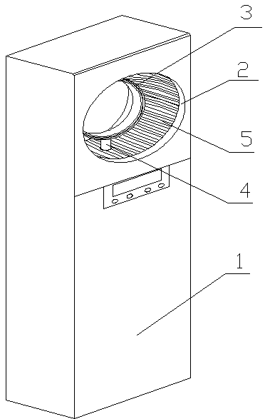
[0024] An internal air inlet type wind tunnel air supply device, which is used as an air supply device for air conditioners, humidifiers, air purifiers, floor fans and other products. It includes a wind tunnel 2 and an air ring 3 arranged in the wind tunnel .

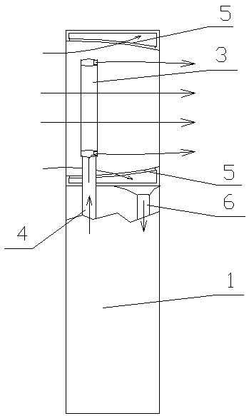
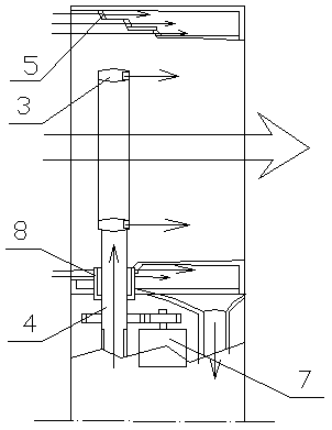
[0025] Different from the wind tunnel structure of the existing bladeless fan, it sets the air inlet 5 on the inner wall of the wind tunnel 2, and the cross section of the air inlet 5 is a slope surface or a multi-layer stepped surface, so the wind tunnel 2 The inlet is larger, while the outlet is smaller. After the air enters the wind tunnel 2, the air close to the inner wall of the wind tunnel is sucked into the inner cavity of the wind tunnel by the air inlet 5, and enters the main engine through the air inlet pipe 4 connected with the inner cavity of the wind tunnel. within 1.

[0026] The h...


PUM


Abstract

An inward air inlet type air tunnel air supply device comprises an air tunnel. A connector connected with a host is formed in the bottom of the air tunnel, an air inlet is formed in the inner wall of the air tunnel and connected with an inner cavity of the air tunnel, and an air inlet pipe is arranged at the lower end of the inner cavity of the air tunnel. An air ring is arranged in the center of the air tunnel, and a high-pressure air outlet is formed in one side of the air ring. An air supply pipe, penetrating the inner wall of the air tunnel, in an inner cavity of the air ring is connected with a high-speed motor and an impeller which are arranged in the host. According to the inward air inlet type air tunnel air supply device, the air inlet is formed in the inner wall of the air tunnel, and when the air inlet works, air sucked into the position near the inner wall of the air tunnel serves as inflow air, flowing of the air in the air tunnel is increased, and the air supply efficiency of the air tunnel is improved; the air outlet is formed in the air tunnel rather than the inner wall of the air tunnel, so that on the one hand, the area of the air inlet is increased, and the amount of the air entering the high-speed motor is increased; and on the other hand, the air outlet is formed in the air tunnel, therefore, the air in the center of the air tunnel can flow better, a part of air between the inner wall of the air tunnel and the air ring can be utilized, and the air supply efficiency is improved.

Description

technical field [0001] The invention relates to an air supply device used for air conditioners, humidifiers, air purifiers and other products, in particular to an inner air inlet type wind tunnel air supply device. Background technique [0002] The wind tunnel has been widely used as an air supply device on bladeless fans. It hides the rotating blades inside the product. There are slit-like air outlets on the inner wall of the wind tunnel, and the high-speed motor rotates to compress the air, forming The high-speed wind is discharged from the slit-shaped air outlet, and further drives the air flow in the wind tunnel, reduces the wind speed, increases the air flow, and forms a stable and continuous wind force. [0003] The air inlet of the existing wind tunnel type air supply device is arranged on the outer wall of the main engine below the wind tunnel, and they suck air through the air inlet on the main engine, and send it into the high-speed motor and the impeller for accel...

Claims


Application Information

Patent Timeline
Patent Type & Authority Patents(China)
IPC IPC(8): F04B41/06
CPCF04D25/08F04F5/16F04F5/46
Inventor 张伟范建平范建良钟至洋
Owner 张伟
Why Eureka
Try Eureka